2427451 - 5580H parking obstacle detection device
The parking sensors provide the driver with information relating to distance when approaching obstacles either in front of or behind the vehicle. This aids parking manoeuvres by identifying obstacles outside the driver's field of view.The information that there is an obstacle and its distance is transmitted to the driver by means of acoustic signals whose frequency depends on the distance from the obstacle.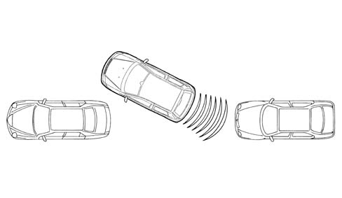
The parking assistance system on the vehicle comprises the following components:
- an electronic control unit;
- 4 ultrasound sensors;
- 1 buzzer
PARKING SENSOR CONTROL UNIT (CPA)
The CPA is an electronic component connected to the rear wiring which carries out functions helping the driver during manoeuvres with reverse gear engaged by detecting any obstacles behind the vehicle. There are interfaces on the CPA for the sensors on the rear bumpers, the trailer control unit and a speaker in the rear part of the vehicle.The control unit has the following connections:
- trailer presence;
- igntion-operated supply
- connections with rear sensors;
- Diagnostic line K
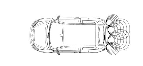
SENSORS
The sensors are incorporated in the bumper by means of special adaptors. The flow of ultrasound waves produced/received by the sensors must not be obstructed therefore:| Tow hooks, bicycle carriers or similar accessories should not interfer with the operating range of the sensors. |
The rear sensors operate in the following conditions:
- key ON;
- reverse gear engaged.
SENSORS
SETTINGS| NB: The sensor sensitivity setting and, consequently, the detection area, is carried out by the supplier. |
ELECTRONIC CONTROL UNIT
The electronic control unit performs the following functions:
- Activating the sensors
- Processing the signals received from the sensors
- Checking the operation of the sensors
- Activating the buzzer
- Managing the diagnostics and test functions

ELECTRONIC CONTROL UNIT
Parking control unit.CONTROL UNIT PINOUT:
| Pin | Signal |
|---|---|
| relay | Left rear exterior sensor signal |
| relay | Left rear interior sensor signal |
| 3 | Right rear interior sensor signal |
| 4 | Right rear exterior sensor signal |
| 5 | Sensor positive |
| 6 | Sensor earth |
| 7 | n.c. |
| 8 | n.c. |
| 9 | n.c. |
| 10 | n.c. |
| 11. | n.c. |
| 12. | Earth |
| 13 | Reversing signal |
| 14 | Activation/Deactivation of system with tow hook (1) fitted |
| 15 | n.c. |
| 16 | n.c. |
| 17 | n.c. |
| 18 | n.c. |
| 19 | n.c. |
| 20 | Diagnostic line K |
| 21 | n.c. |
| 22 | Buzzer signal (-) |
| 23 | Buzzer (+) |
| 24 | n.c. |
| 25 | n.c. |
| 26 | n.c. |
ULTRASOUND SENSORS
The sensors are ultrasoud transducers working like intelligent transmitters and receivers of ultrasound impulses. Both the impulse frequency and voltage is generated in the transducer.The impulses emitted are reflected by any obstacles; the transducer therefore receives an echo which is amplified and converted into a digital signal and sent to the electronic control unit via the same line used for the transmission request.Each sensor can also be operated as a receiver only, in oder to carry out a triangular measurement between two sensors. This technique allows for improved detection of small obstacles and in situations featuring critical reflections.The sensors all have the same electrical and mechanical properties: the maximum detection distance for each sensor can be adapted using software depending on the location of the actual sensor.SENSOR PINOUT
| Pin | Signal |
|---|---|
| relay | Sensor signal |
| relay | Earth |
| 3 | Sensor supply voltage |
ACOUSTIC SIGNALLER
The acoustic signaller (buzzer) communicates information concerning distance, the activation of the system and any fault. The buzzer is located inside the passenger compartment.The frequency and the volume can be controlled by the control unit.
MEASURING THE DISTANCE OF OBSTACLES
The electronic control unit determines the measurement timing; it operates the senors which convert the control unit electrical signals into ultrasound impulse trains, with a cadence that varies from 3 to 10 measuring processes per second.The signal, reflected by any obstacles, is received by the sensor and amplified, converted into a digital signal and sent, in this format, to the electronic control unit.The control unit compares the signal emitted with the one received and, using suitable algorithms, calculates the time that elapses between the emission of the signal and the receipt of the echo. This information is translated into distance and communicated to the driver by means of acoustic warnings. The reflection from the ground is ignored unless it has the properties of an obstacle.SELF-DIAGNOSIS
The control unit carries out an autodiagnostic test when it is switched on. The sensors are diagnosed each time they are activated.RECOVERY STRATEGIES
The sensors and the wiring are continuously diagnosed during the operation of the system. A fault in even only one sensor will inhibit the operation of the entire system.ACTIVATION AND DEACTIVATION OF THE SYSTEM
When the control unit is switched on (key-on and reverse gear engaged), an autodiagnostic test and a test on all the surrounding components is carried out. The system is ready to use in less than 0.5 seconds.The distance measurements only take place when the system is activated.The system is activated when the following two conditions occur:
- Key ON
- Reverse gear engaged