2429772 - 2110B20 manual gearbox (5 speed) with differential - dismantle and rebuild - wash and check parts - replace synchronisers and internal controls if necessary
 | Name | Country |
|---|---|---|
| 1b | Mount | 1.870.689.000 |
| Name | Country |
|---|---|---|
| 1c | Gearbox mount | 1.860.873.000 |

| Name | Country |
|---|---|---|
| - | Gearbox mount | 1.860.873.000 |
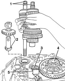
| Two operators are needed for this operation. |
| Name | Country |
|---|---|---|
| 1b | Rotating stand | 1.871.000.000 |
| Name | Country |
|---|---|---|
| 1c | Support | 1.871.001.014 |
| Two operators are needed for this operation. |
| Name | Country |
|---|---|---|
| - | Rotating stand | 1.871.000.000 |
| Name | Country |
|---|---|---|
| 1b | Support | 1.871.001.014 |

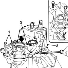
| Use a drier to facilitate the removal of the sealant. |

| Name | Country |
|---|---|---|
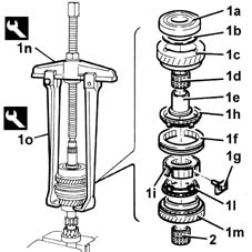
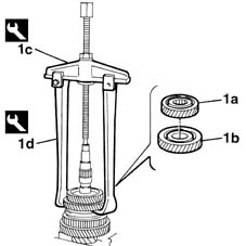
| 1b | Brackets | 1.840.005.308 |
| Name | Country |
|---|---|---|
| 1c | Extractor | 1.840.005.001 |
| Name | Country |
|---|---|---|
| 1d | Counter weight | 1.840.206.000 |

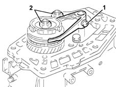
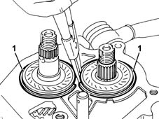
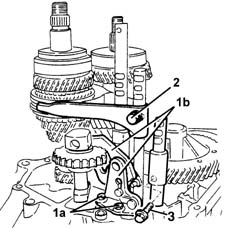
| The simultaneous engagement of two gears will cause the gearbox shafts to lock. |
| Positioning the selector fork for 5 th speed in neutral is necessary to prevent the synchronizer rollers from being lost. |
| The simultaneous engagement of two gears will cause the gearbox shafts to lock. |
| Positioning the selector fork for 5 th speed in neutral is necessary to prevent the synchronizer rollers from being lost. |

| Name | Country |
|---|---|---|
| 2b | Extractor | 1.840.005.400 |

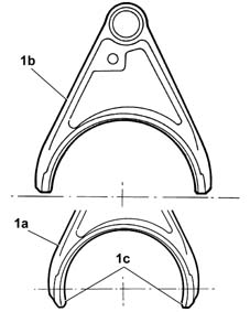
| Starting from the month of June 1998, a new selector fork for engaging 5 th speed has been adopted on C510-C513 type gearboxes which replaces the selector fork fitted previously. The new selector fork (no. 46549946) should be fitted on gearboxes where it is already used (production from 6/98), but it is interchangeable with the previous selector fork (fitted on gearboxes produced before 6/98). The previous selector fork (which should only be fitted on gearboxes produced before 6/98) is available from the Parts Division until stocks run out. |

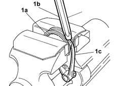
| take care not to damage the tapered part of the sleeve and the ends of the selector fork with the drift. |
| Name | Country |
|---|---|---|
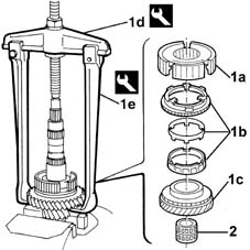
| 1d | Extractor | 1.840.005.400 |

| Name | Country |
|---|---|---|
| 1b | Extractor | 1.845.057.000 |


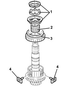
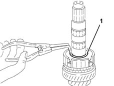
| To facilitate the fitting of the circlips, place them with their openings at the front. |


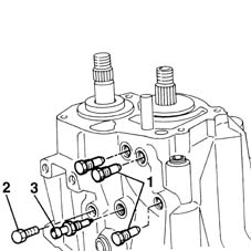
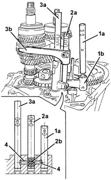
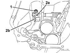
| If the rod offers resistance to being withdrawn, move the other rods (2a) and (3a) to shift the pawls (4) and (2b). |
| Work carefully to avoid the pawl (2b) accidentally falling out. |
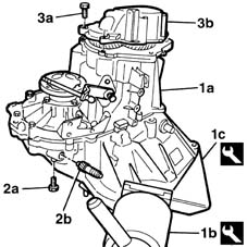
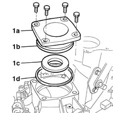
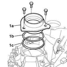
| The gasket and the seal should always be replaced. |


| Replace the inner and outer bushes each time the clearance for the thrust bearing control shaft is excessive. |

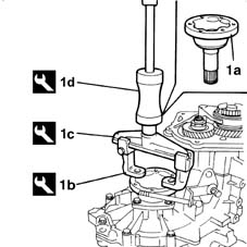
| Name | Country |
|---|---|---|
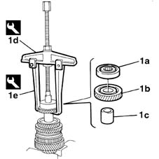
| 1d | Extractor | 1.840.005.002 |
| Name | Country |
|---|---|---|
| 1e | Clamps | 1.840.005.303 |
| Name | Country |
|---|---|---|
| 1c | Extractor | 1.840.005.002 |
| Name | Country |
|---|---|---|
| 1d | Clamps | 1.840.005.306 |

| Name | Country |
|---|---|---|
| 2c | Extractor | 1.840.005.002 |
| Name | Country |
|---|---|---|
| 2d | Clamps | 1.840.005.301 |
| Name | Country |
|---|---|---|
| 2e | Extractor | 1.842.133.000 |

| When refitting, replace the circplip. |
| Name | Country |
|---|---|---|
| 1c | Extractor | 1.840.005.002 |
| Name | Country |
|---|---|---|
| 1d | Clamps | 1.840.005.303 |

| Name | Country |
|---|---|---|
| 1d | Extractor | 1.840.005.002 |
| Name | Country |
|---|---|---|
| 1e | Clamps | 1.840.005.306 |
| The layshaft front bearing inner race should not be refaced; if necessary, replace it together with the layshaft. |
| Name | Country |
|---|---|---|
| 2d | Extractor | 1.840.005.002 |
| Name | Country |
|---|---|---|
| 2e | Clamps | 1.840.005.306 |
| For the removal of the layshaft front bearing, see - 2110B32 manual gearbox (5 speed) with differential - dismantle and rebuild - wash and check parts - replace synchronisers, inner controls, gears, shafts and bearings |

| Name | Country |
|---|---|---|
| 1n | Extractor | 1.840.005.002 |
| Name | Country |
|---|---|---|
| 1o | Clamps | 1.840.005.306 |