2427400 - 1060F injectors and lines
INJECTORS
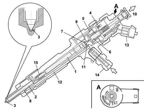
The injectors are fitted on the cylinder
head and operated by the injection control unit.The injectors can be divided into
two sections:
- actuator/nozzle consisting of a pressure rod (1), pin
(2) and jet (3)
- solenoid valve consisting of a coil (4) and pilot valve
(5).
The operation of the injector can be divided
into three stages.REST POSITION. The coil (4) is de-energized
and the shutter (6) is in the closed position and does not allow
the introduction of fuel into cylinder Fc > Fa (Fc: due to the
line pressure acting on control area 7 of the rod 1; Fa: due to
the line pressure acting in supply volume (8).START OF INJECTION, the coil (4) is energized
and causes the shutter (6) to be raised.The control volume (9) fuel flows towards
the return manifold (10) causing a decrease in pressure in the control
area (7). At the same time, the line pressure exerts a force Fa
> Fc in the supply volume (8), via the supply duct (12), causing
the raising of the pin (2) with the consequent introduction of fuel
into the cylinders.END OF INJECTION. The coil (4) is de-energized
and returns the shutter (6) to the closed position which recreates
an equilibrium with forces which return the pin (2) to the closed
position and consequently end the injection.
IMA CLASSIFICATION
During the test stage the injector specifications
are checked in different pressure/flow rate conditions. Any injectors
that do not meet a certain standard are discarded; the remaining
ones are classified ausing an alphanumerical code with nine digits known
as an IMA code etched by laser on the top part of the magnet.When fitted in the vehicle the control unit
must memorize the individual code and if one or more of the injectors
is replaced in a service situation the different code must be entered
during the diagnostic equipment.1 - Pressure rod
2 - Pin
3 - Jet
4 - Coil
5 - Valve
6 - Spherical plunger
7 - Control area
8 - Supply volume
9 - Control volume
10 - Fuel return - low pressure
11 - Control duct
12 - Supply duct
13 - Electrical connection
14 - Fuel inlet connector - high pressure
15 - Spring
SINGLE FUEL MANIFOLD PIPE
The single fuel manifold pipe (rail) is
fitted on the inlet side cylinder head.With its volume of around 20 cm3
it dampens the fuel pressure oscillations due to:
- the operation of the pressure pump
- injector opening.
The fuel pressure sensor is fitted on one
side of the supply manifold, while the pressure regulator is fitted
on the other side Characteristic of working principle 1060G pressure pump electric
control.The (high pressure) hydraulic connections
between the manifold-pump and manifold-injectors are made by means
of steel pipes with an internal diameter of 2 mm and an external
diameter of 6 mm.