2427401 - 1060G pressure pump electric control
Injection control unit (MJD - 6JF Magneti Marelli
common rail)
It is fitted in the engine compartment.The control unit is the 'flash EPROM' type,
i.e. reprogrammable from the outside without intervening on the
hardware.The injection control unit integrates the
absolute pressure sensor.PIN-OUT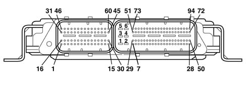
SPECIFCATIONS
This is fitted on the cylinder block/crankcase,
'facing' the phonic wheel on the engine flywheel.It is of the inductive type, i.e. it functions
by means of the variation in the magnetic field generated by the
passage of the teeth of the flywheel (60-2 teeth).The fuel injection control unit uses
the rpm sensor to:
- determine the rotation speed;
- determine the angle of the crankshaft.
SPECIFCATIONS
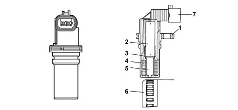
The figure shows the rpm sensor components.1 - Brass bush
2 - Permanent magnet
3 - Plastic sensor casing
4 - Coil winding
5 - Polar core
6 - Ring gear or flywheel
7 - Coaxial two-wire cable or electrical connection
SPECIFCATIONS
PIN-OUT| Pin | Name | Signal type |
|---|
| 1 | Phonic wheel signal (A) | Frequency output |
| 2 | Phonic wheel signal (B) | Frequency output |
TECHNICAL SPECIFICATIONS
Winding resistance 790 Ohm ± 20%Winding resistance 680 mH ± 20% (f=1kHz)The distance (gap) for obtaining correct
signals, between the end of the sensor and the flywheel, should
be between 0.8 and 1.5 mm.This gap is not adjustable, so if a value
outside the tolerance range is measured, check the condition of
the sensor and the flywheel.The graph shows sthe sensor output signal
in relation to the horizontal development of the phonic wheel.1 - Toothed wheel profile
2 - Rpm sensor signal
3 - Reference tooth
4 - TDC recognition point
OPERATION
The passage from full to empty, due to the
presence or absence of the tooth, causes a variation in the magnetic
flow which is sufficient to generate an induced alternating voltage,
resulting from the count of teeth located on a ring (or phonic wheel).The frequency and range of the voltage sent
to the electronic control unit provides it with the angular speed
of the crankshaft.
SPECIFCATIONS
Hall effect, fitted on the cylinder head
and 'facing' the cams.This pulley comprises a tooth which enables
the timing sensor to indicate the engine's timing position.The fuel injection control unit uses the
timing sensor signal to recognise the TDC at the end of compression,
and during starting so as to synchronise the engine management control
unit with the engine.The sensor is fitted near the exhaust camshaft.
OPERATING
A semiconducting layer, through which current
passes, immersed in a perpendicular magnetic field (force lines
perpendicular to the current direction), generates at its ends a
difference in potential known as Hall voltage.If the intensity of the current remains
constant, the voltage generated only depends on the intensity of
the magnetic field; the intensity of the field simply has to vary
periodically to produce a modulated electrical signal, whose frequency
is proportional to the speed with which it changes magnetic field.
To obtain this change, a tooth on the inside of the pulley moves close
to the sensor.
OPERATING
PIN-OUT| Pin | Name | Signal type |
|---|
| 1 | Earth | Earth |
| 2 | Timing signal | Frequency output |
| 3 | Fuel system | 12 V input |
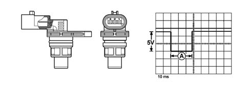
In the specific case of the timing sensor,
it is supplied by the engine management control unit at 5 V.Whenever the rotor passes in front of the
sensor, a Hall-effect change in output voltage from the sensor is
generated; this change takes place throughout the duration of the
passage of the rotor in front of the sensor, after which the signal
returns to the initial value (5V).
SPECIFCATIONS
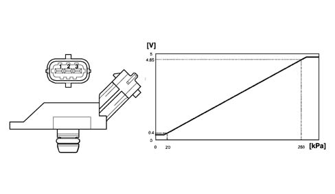
The turbocharging pressure sensor is fitted
on the inlet manifold and allows an inlet pressure of up to 1.5
bar to be measured (corresponding to 2.5 bar absolute).The sensitive element consists of a piezoresistive
eleent whose signal is amplified by an electronic circuit integrated
in the sensor. The sensor is supplied directly by the electronic
control unit with a voltage of 5 V, and as an output supplies a
voltage directly proportional to the turbocharging pressure.
SPECIFCATIONS
Excess pressure sensor pin out| Pin | Name | Signal type |
|---|
| 1 | Fuel system | 5 V supply |
| 2 | Earth | Earth |
| 3 | Sensor output | Analogue output |
SPECIFCATIONS
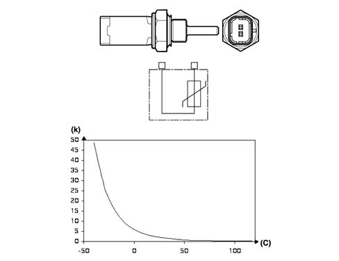
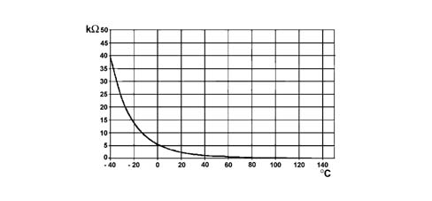
It is fitted on the thermostatic cup and
measures the temperature of the coolant by means of an NTC which
has a negative resistance coefficient.
SPECIFCATIONS
Engine coolant temperature sensor specifications| Temperature (C°) | Resistance (kOhm) |
|---|
| - 40 | 48.80 |
| - 30 | 27.41 |
| -20 | 15.97 |
| - 10 | 9.62 |
| 0 | 5.97 |
| 10 | 3.81 |
| 20 | 2.5 |
| 30 | 1.68 |
| 40 | 1.15 |
| 50 | 0.81 |
| 60 | 0.58 |
| 70 | 0.42 |
| 80 | 0.31 |
| 90 | 0.23 |
| 100 | 0.18 |
| 110 | 0.14 |
| 120 | 0.11 |
| 130 | 0.08 |
SPECIFCATIONS
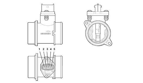
The flow meter is located on the air inlet
duct and is of the 'hot film' type.An arrow on the flow meter outer casing
indicates the direction of the air flow.
SPECIFCATIONS
Air flow meter pin out| Pin | Name | Signal type |
|---|
| 1 | Fuel temperature | Analogue output |
| 2 | Fuel system | 12 V supply |
| 3 | Earth | Earth |
| 4 | Reference voltage | 5 V |
| 5 | Sensor output | Analogue output |
 | The air flow meter cannot be dismantled. |
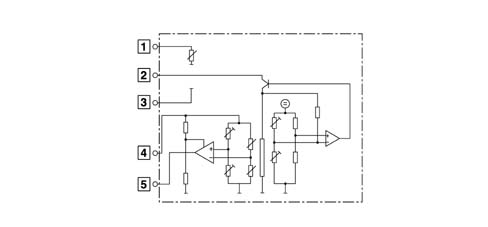
OPERATION
The operating principle is based on a diaphragm
located in a measuring duct through which the intake air entering
the engine flows.The hot film diaphragm is kept at a constant
temperature (about 120°C above the incoming air temperature) by
the heating resistor.The air mass passing through the measuring
duct tends to draw heat from the diaphragm, so to keep the latter
at a constant temperature, some current must flow through the resistor.The figure shows the general diagram of
the flow meter's sensitive element.
OPERATION
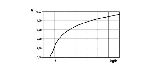
The platinum hot-film sensor is a PTC (positive
temperature coefficient) thermal resistor, i.e. a resistor whose
value increases as the temperature increases.As the quantity of air taken in increases,
the amount of heat drawn from the sensor increases, so there is
a reduction in the sensor's resistance. As this is inserted in a
'bridge' measurement circuit, it causes an increase in the output
voltage, measured by the ECU to calculate the volume of air drawn
in by the engine.The flow meter is also able to distinguish
the direction of the air flow, so the information relates to the
actual quantity of air drawn in by the engine, unaffected by any
turbulence.
OPERATION
Air flow meter specificationsThe air temperature sensor is built into
the flow meter. This sensor is of the NTC type: the nominal resistance
is 2000 Ohm at a temperature of 25 °C.| Temperature (C°) | Resistance (kOhm) |
|---|
| - 40 | 39.26 |
| - 30 | 22.96 |
| -20 | 13.85 |
| - 10 | 8.609 |
| 0 | 5.499 |
| 10 | 3.604 |
| 20 | 2.42 |
| 30 | 1.662 |
| 40 | 1.166 |
| 50 | 0.835 |
| 60 | 0.609 |
| 70 | 0.452 |
| 80 | 0.34 |
| 90 | 0.261 |
| 100 | 0.202 |
| 110 | 0.159 |
| 120 | 0.127 |
| 130 | 0.102 |
OPERATION
. | The flow meter directly measures
the air mass (not volume), thus eliminating problems of temperature,
altitude, pressure, etc. |
Specifications
It is built into the fuel heater and measures
the temperature of the coolant by means of an NTC thermistor which
has a negative resistance coefficient.
Specifications
Fuel temperature sensor pin out| Pin | Name | Signal type |
|---|
| 1 | Sensor earth | Earth |
| 2 | Temperature signal | Analogue output |
Fuel temperature sensor specifications| Temperature (C°) | Resistance (kOhm) |
|---|
| - 40 | 48.80 |
| - 30 | 27.41 |
| -20 | 15.97 |
| - 10 | 9.62 |
| 0 | 5.97 |
| 10 | 3.81 |
| 20 | 2.5 |
| 30 | 1.68 |
| 40 | 1.15 |
| 50 | 0.81 |
| 60 | 0.58 |
| 70 | 0.42 |
| 80 | 0.31 |
| 90 | 0.23 |
| 100 | 0.18 |
| 110 | 0.14 |
| 120 | 0.11 |
| 130 | 0.08 |
The sensor is based on semiconductor technology;
so if the sensor temperature increases as the fuel temperature increases, the
resistance decreases.As the variation in resistance is not linear,
for the same temperature increment, it is higher for low temperatures
than for high temperatures.
SPECIFCATIONS
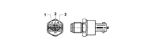
It is fitted at the end of the 'rail'
fuel distribution manifold and has the task of supplying the injection
control unit with a 'feedback' signal to:
- regulate the injection pressure
- regulating injection duration.
SPECIFCATIONS
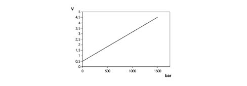
The sensor is supplied directly by the engine
management control unit with a voltage of 5 V. The output voltage
varies linearly between 0.5 V (0 bar) and 4.5 V (1500 bar).
SPECIFCATIONS
Fuel pressure sensor pin out| Pin | Name | Signal type |
|---|
| 1 | Earth | Earth |
| 2 | Sensor output | Analogue output |
| 3 | Fuel system | 5 V supply |
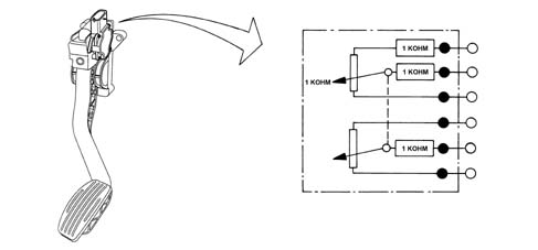
CONSTRUCTION FEATURES
The sensor consists of a casing, secured
to the accelerator pedal mount, which contains a shaft, in an axial
position, connected to two potentiometers: one main one and one
safety one.There is a coil spring on the shaft which
guarantees the correct resistance to the pressure whilst a second
spring ensures the return on release.The redundant reading of the signal makes
it possible to continuously monitor the plausibility of the values
measured, so as to ensure completely safe driving, even in the event
of a fault.
OPERATION
The position of the accelerator pedal is
transformed into an electrical voltage signal and is sent to the
fuel injection control unit by the potentiometer connected to the
accelerator pedal.The accelerator pedal position signal is
processed together with the information relating to the rpm, to
obtain the fuel injection times and relevant pressure.| Pin | Name | Signal type |
|---|
| relay | Track 2 supply | 5 V input |
| 2 | Track 1 supply | 5 V input |
| 3 | Track 1 earth | Earth |
| 4 | Track 1 signal | Analogue output |
| 5 | Track 2 earth | Earth |
| 6 | Track 2 signal | Analogue output |
BOSCH SENSOR TECHNICAL SPECIFICATIONS
Supply voltage: 5V ± 0.3VResistance at potentiometer slide terminals:
: 1 kOhm ± 0.4 kOhmTrack 1 resistance: 1.2 kOhm ± 0.4 kOhmTrack 2 resistance: 1.7 kOhm ± 0.8 kOhm
HELLA SENSOR TECHNICAL SPECIFICATIONS
Supply voltage: 5V ± 0.3VResistance at potentiometer slide terminals:
: 1 kOhm ± 0.4 kOhmTrack 1 resistance: 0.9 kOhm ± 35% ....1.4
kOhm ± 35%Track 2 resistance: 1.2 kOhm ± 35% ....2.0
kOhm ± 35%
CONSTRUCTION FEATURES
The fuel pressure regulator is fitted on
the rail and regulates the fuel pressure in accordance with commands
from the engine management control unit, via a ball valve which
discharges the fuel ont he low-pressure line to the fuel tank.
CONSTRUCTION FEATURES
The fuel pressure regulator contains a solenoid
which is controlled by the engine management control unit by the
PWM method (carrier 1 kHz). When the duty cycle is set to 0%, the
solenoid is not supplied: there is minimum pressure in the rail because
of the preload of the ball valve spring.
ELECTRICAL SPECIFICATIONS
Resistance: 2.07 - 2.53 (ohm) at 20 °CMaximum current 2.5 AMinimum pressure not supplied 50 bar
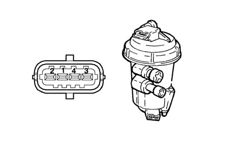
CONSTRUCTION FEATURES
The electric fuel pump supplies the high-pressure
pump. It is fully immersed in the fuel in the fuel tank. The pump
assembly is designed so as to obtain the maximum fuel level in the
suction area.This function is achieved by a Venturi located
on the return pipe to the suction area, rather than to the fuel
tank. The pumping unit is of the roller type and permits a capacity
of 160 litres/hour.The pump comprises a permanent-magnet electric
motor which is continuously supplied when the engine is on. The
fuel sent to the high-pressure pump which has not been used flows
back into the tank through a pressure-relief valve mounted on the
filter unit.The pump has a further pressure-relief valve,
so as to avoid damage to the pumping unit if the delivery pipe becomes blocked.
TECHNICAL SPECIFICATIONS
Absorbed current < = 4.6 A (supply voltage
13 V)Capacity > = 150 l/hWorking pressure 200 - 400 kPa
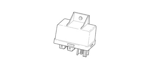
CONSTRUCTION FEATURES
The device interfaces with and is controlled
by the engine management system in accordance with the EOBD protocol.
It has been designed to carry out all the operating and monitoring
functions for the operation of the individual heater plugs during
the pre-heating stage for diesel engines.The control unit comprises a protection
against high currents and high voltrages, and has a control logic
which, in the event of a fault, acts as an auto-reset electronic
fuse.Because of its thermal characteristics and
resistance to external agents, the device can be fitted directly
in the engine compartment.The control unit is protected on all terminals
against the possible reversed connection of battery terminals, and
is built in such a way as to withstand all stresses occurring in
the vehicle.
CONSTRUCTION FEATURES
The unit has the following connecting termnals:| Terminal | Name |
|---|
| 30 | Direct connection to battery positive (+Vbat)
for supplying the plugs |
| G1, G2, G3, G4 | Output for plug connections |
| 86 | Supply from engine management control unit |
| 31 | Earth connectioni (GND) |
| ST | Input for start to control coming from engine
management control unit |
| K | Input for start to control coming from engine
management control unit |
| DI | Output for diagnosis to engine management
control unit |
CONSTRUCTION FEATURES
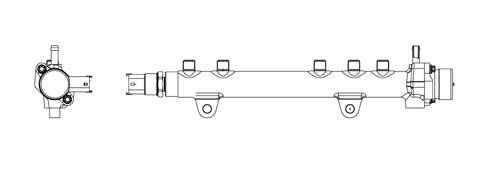
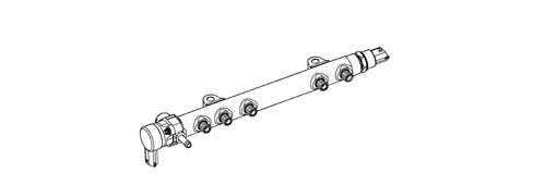
The rail consists of a forged steel tube
designed to withstand the high operating pressures in the high-pressure
system.
CONSTRUCTION FEATURES
The internal volume in the rail is cm3:
this volume has been determined so as to minimise pressure peaks
due to the injection process, without slowing down the commands
to change the fuel pressure set by the engine management control
unit, in order to optimise combustion. The fuel from the high-pressure pump reaches
the rail and is then taken to the injectors. A pressure sensor and
the high-pressure regulator are mounted on the rail.
CONSTRUCTION FEATURES
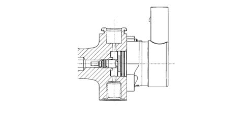
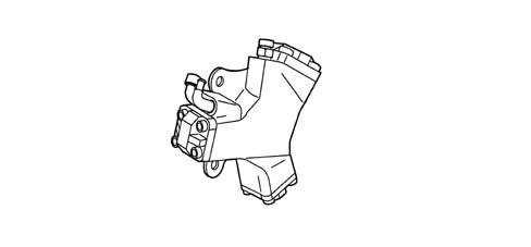
The high-pressure pump is of the CP1 Compact
type with three radial pistons The capacity is 567 mm3/revolution
and the rotation speed, being mounted on the camshaft, is equal
to half the speed of rotation of the crankshaft (reduction ratio
2:1). The pump is lubricated and cooled by the flow of fuel passing
through it: the necessary flow rate is provided by the low-pressure
pump. This supplies the pump with a quantity of fuel which always
exceeds the engine's requirement, so as to create a recirculation
of fuel towards the tank, and so the pump is lubricated (as a priority)
and cooled.The movement of the pistons is deterined
by a cam joined to the pump shaft: this drives a polygonal ring
which acts on the piston small end.Each pumping unit has an inlet plate valve
and a delivery supply valve.The pump comprises a shutoff valve: this
protects the pump in the event of a low flow rate from the low-pressure
supply, thus ensuring lubrication to the pumping units and cam mechanism.
TECHNICAL SPECIFICATIONS
Radial pump with 3 pumping unitsCapacity 567 [mm3/revolution]Efficiency: > 79% at 1350 bar at 1000
rpmNominal pressure: 1350 bar
CONSTRUCTION FEATURES
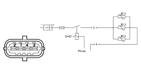
The diesel heater is built into the diesel
filter cover and comprises three resistors which are supplied by
the control unit in accordance with the signal from the fuel temperature
sensor.
CONSTRUCTION FEATURES
DIESEL FILTER CONNECTOR PIN-OU| Pin | Name | Signal type |
|---|
| 3 | Fuel system | 12V |
| 4 | Earth | Earth |
CONSTRUCTION FEATURES
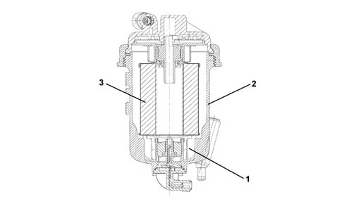
Inserted in the diesel filter container
casing, at the bottom, it indicates the presence of water via the
warning light on the instrument panel.1 - Water presence sensor
2 - Diesel filter casing
3 - Filter element