2429968 - Introduction - PANELS AND FRAME
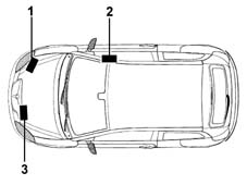
Vehicle identification data
The vehicle has the following identification
plates:
- 1. Vehicle identification data plate
- 2. Bodyshell marking
- 3. Bodywork paint identification plate.
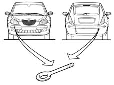
Towing points
The vehicle has two threaded
sockets, one at the front and one at the rear, for fitting the tow
hook which is housed in the compartment in the spare wheel in the
luggage compartment under the carpet.
Towing points
. | When towing the vehicle, the laws
governing towing and road traffic must be obeyed. Before towing,
make sure that the tow hook is fully tightened. Thoroughly clean
the threaded housing before tightening the tow hook. Turn the ignition key
to the ON position and then to the OFF position and DO NOT EXTRACT
IT !When the key is extracted, the steering lock is immediately engaged
and it is consequently impossible to steer the wheels. Whilst towing,
as the brake servo is not working, greater force will have to be
exerted on the brake pedal. The towing vehicle should be driven
as smoothly as possible to prevent the two vehicles striking one
another. Do not use flexible cables for towing and avoid jerking.
During towing operations, check that the tow cable coupling does
not damage parts with which it comes into contact. |
| For versions with automatic transmission, observe
the following additional instructions: 1) place the gear lever
in position N; 2) maintain a towing speed less than 30 km/h; 3)
the maximum towing distance is 20 km For greater distances, raise
the front end of the car to prevent damage to the transmission due
to insufficient lubrication. |
| After having raised the vehicle,
support it using safety stands.Before lifting the front of the vehicle,
lock the wheels using chocks in behind the rear wheels. |
| When lifting the front of the
vehicle, this may be done only by positioning the lift arm beneath
the gearbox-differential unit and placing a wooden or rubber block
between the arm and the vehicle. |
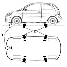
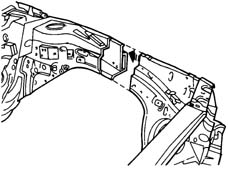
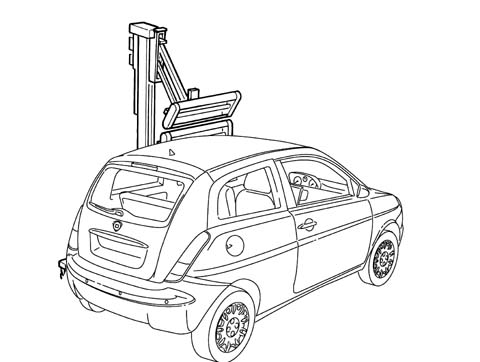
Vehicle lifting points
To lift the vehicle using a ramp
or hoist, place the ends of the arms or hoist only in the areas
shown in the figure.With workshop liftWith lift with arms
Vehicle lifting points
. | Before lifting the vehicle using
portable lifts, lock the wheels by placing chocks in front of (behind) the
front (rear) wheels. |
After having raised the vehicle, support
it using safety stands.
General safety warnings
The activities connected with
repairing the bodywork involve the use of equipment and tools in
addition to the handling of chemical products and substances for
which the supplier's instructions must be followed.It is therefore necessary to pay
special attention to:
- the correct use of materials, instruments and equipment:
before carrying out any sort of operation, read the instruction
manuals carefully and follow the accident prevention and safety
instructions with great care.
- The workplaces for carrying out operations, which should
have appropriate ventilation systems which satisfy the legal requirements
concerning air exchange, the filtration of harmful substances (solvents)
and the reduction of dust levels.
- The handling of dangerous substances which should be
carried out in accordance with the supplier's instructions and recommendations.
- The collection and disposal of refuse which should be carried
out in accordance with the laws in force.
When working with and handling harmful and
dangerous substances, the appropriate safety equipment should be employed
(clothing, masks, gloves, goggles, etc.).
Vehicle repair operating cycles
The vehicle repair operating cycles
usually consist of the following stages:
- checking the vehicle measurements;
- cutting/removing damaged elements and preparing the
bodyshell for welding;
- welding replacement elements;
- preparing for painting;
- painting;
- renewing the anti-corrosion treatments;
- sound insulation, sealants.
CHECKING AND RESTORING THE VEHICLE MEASUREMENTS
This is the first stage of the
repair operation during which the deformations suffered by the bodyshell
are measured and evaluated and the elements involved are identified.During this stage the first actual repair
operation is carried out: pulling the bodyshell to restore the measurements before
cutting and removing the damaged elements.
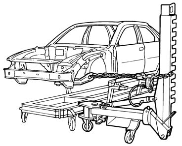
PULLING THE BODYSHELL
Pulling the bodyshell, to restore
the measurements, is carried out on straightening benchs where it
is possible to secure the bodyshell using vices and attachments
which should be fixed according to specific methods for each vehicle,
with instructions provided by each supplier.Jigs are used to check the measurements
of the bodyshell. They are positioned at specified points, and are
used to check the measurements indicated by the jig manufacturer for
each model, or alternatively the vehicle's own measurements given
in the section 'Descriptions and Operation'.Example of a possible straightening bench
configuration.
General repair instructions
| Before carrying out any sort of
operation on the vehicle, disconnect the battery terminals. |
For safety reasons and for a better
quality repair, IT IS PROHIBITED TO:
- replace structural parts of the bodyshell without using a
repair bench. The use of the bench makes it possible to guarantee
the restructuring of the vehicle with the original manufacturing
measurements, ensuring the correct position of the forecarriage
and back-carriage elements.
- heat the structural parts of the bodyshell to straighten them.
- cut and weld, edge to edge, any bodywork element and
reinforcement on the same line.
Remove the damaged elements, cutting them
on the joins, following the cutting lines given in the Service Manual. Carried
out correctly, the operation involves wasting a few centimetres
between the two cutting lines in order to improve the distribution
of the fusible points created by the welding.The diagram below illustrates a possible
implementation.
General repair instructions
. | The removal of the damaged elements
is the repair operation during which the potentially most dangerous
equipment is used. Before carrying out any sort of operation, read
the instruction manuals, the safety instructions and the manufacturer's
warnings which come with the equipment very carefully and follow
all the accident prevention and safety instructions to the letter. |
The use of the following is required
for the removal of damaged body panels:
- hack-sawing machines;
- circular saws;
- power chisels (only in case of need);
- plasma-arc cutting systems;
- electric drills;
- milling machines;
- grinding machines;
- dolly blocks and hammers;
- disc grinding wheels;
- air purifiers / extractor systems.
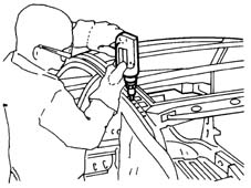
HACK-SAWING MACHINE
This type of saw makes it possible
to carry out fast and precise cutting, with the possibility of regulating
the speed of the blade to suit different situations. Example of the use of a hack-sawing machine
OSCILLATING CIRCULAR SAW
An oscillating saw is used in
cases where high cutting precision is required; for example, when
you need to replace the sheet metal of a box section that is laid
over a panel which must not be damaged. By adjusting the speed and the
number of oscillations it is possible to achieve the precision required
according to the conditions of use. The high level of safety of
this instrument makes it advisable to use it as an alternative to
other types of saws.Example of an oscillating circular saw
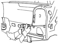
POWER CHISEL
A pneumatic chisel is used to remove
parts of body panels; it is advisable to use it:
- when it is not possible to use a power saw, milling machine
or drill; for example, when a panel that must not be damaged lies
behind the panel that requires cutting;
- when it is possible to directly separate the welded panels,
inserting the power chisel between the two panels along the join
edge in order not to leave edges which need removing later on.
The different attachments increase its versatility.Example of the use of a power chisel
PLASMA-ARC CUTTING SYSTEM
This cutting system, achieved
through the combined effect of an electric arc and gas or a mixture
of gases, is used whenever it is necessary to cut rather large panels. Depending
on the thickness of the panel and the depth of the cut, adjust the
current and the gas flow following the instructions in the Manufacturer's
booklet. | The use of a plasma-arc cutting
system requires the use of an extractor system to get rid of the fumes
and harmful gases. |
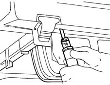
ELECTRIC DRILL
An electric drill is normally
used in cases where a milling machine cannot be used; the correct
use of the drill to remove spot welds if several panels are superimposed
is illustrated in the diagrams below. The attachment to be used
in these operations is identical to the one fitted on the milling
machine. The spot weld should be marked using a drift, in order
to provide a support point for the centring bit, this prevents the
drill moving away from the spot and damaging the surrounding area;
force should be exerted on the cutter until the depth reached is
slightly greater than the thickness of the panel which should be
removed (see diagram below).Example of the use of an electric drill
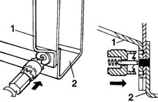
ELECTRIC DRILL
Example of the correct usage
of a milling cutter
1. Panel to be removed.
2. Box section panel preventing the use of a milling cutter.
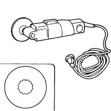
MILLING CUTTER
A milling cutter for removing
weld spots should be used after cutting the panel to be replaced
in order to allow the removal of the panel offcuts remaining on
the edges of the bodyshell. The milling cutter acts on the panel which
constitutes the offcut, cutting it as far as the panel underneath
and thereby isolating the spot weld.After the reduction of all the spot welds.
the offcut is removed using pliers.To facilitate the operation, use a cutting
speed of around 1000 rpm.Adjust the depth of the cutting using the
special screw.Example of the use of a milling cutter
MILLING CUTTER
 | Do not drill matching components.
If holes are made by mistake, close them by (MIG) welding. The presence
of holes reduces the strength of the component involved and can
also give rise to the penetration of water and corrosive agents. |
DOLLY BLOCKS AND LEVERS
These instruments are used when
panels need to be straightened by beating, in order to have a counter-action point
to support the panel. Dolly blocks are designed so that they adjust
to the different panel conformations and, when the working area
permits, they can replace a hammer.Levers are used in the same way as dolly
blocks, however they are designed so that they can be introduced
through restricted openings and spaces to get to areas which are difficult
to reach.Dolly blocks and levers are also used to
eliminate distortions from the edges of panels which are not removed thereby
allowing correct matching with the replaced panels, avoiding weakening
the structure.
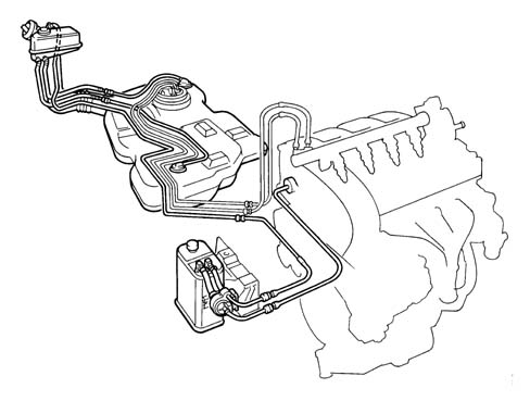
Welding replacement elements
| If welding operations or work
which could produce flames near the fuel system components illustrated
in the diagram or other flammable parts of the vehicle need to be
carried out, the parts involved must be removed from the vehicle and
the free pipe connections sealed if the connectors are removed.
Disconnect the electronic control units (I.E., ABS, Air Bag, Air
conditioning, Alarm, etc.) which could be damaged during the work. |
Parts of the fuel system
Welding replacement elements
Welding bodywork elements should
be carried out, according to requirements, using different methods:
- Spot welding;
- Seam (MIG) welding;
Brazing.
EQUIPMENT
The following equipment is used for
these operations:
- welding guns;
- seam (MIG) welders;
- oxyacetylene torches (brazing).
INTRODUCTION TO ELECTRICAL SPOT WELDING
In electrical spot welding the
heat needed to melt the metal is supplied by the resistance to the
current flow provided by the actual metal.Spot welding is carried out to panels where
the join edges overlap and the panel metal melts; no metal filler
is therefore needed for this type of welding. In areas where three or
more panels overlap, spot welding should be repeated for a second
time.The type of join produced is not continuous;
to create a join with good mechanical strength the spot welds must
be correctly spaced following precise instructions (see tables below).
SPOT WELDING
In the case of spot welding, check::
- that the arms are correctly aligned;
- that the diameter of the edges of the electrodes is
correct;
the planarity and that the weld edges are
correctly matched; the correct welding sequence. | Before welding, apply electro-weldable
galvanizing protection to the edges of the join to protect the box
sections from corrosion. |
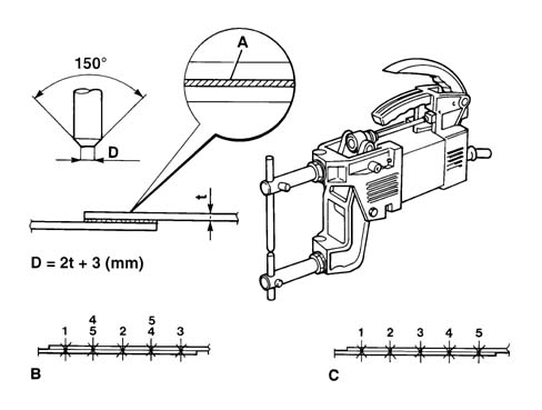
Spot welder, geometric characteristics of
the electrode according to the thickness of the panel and the welding sequence.
A. Electro-weldable galvanizing protective
B. Correct welding sequence
C. Incorrect welding sequence
D. Electrode dimensions
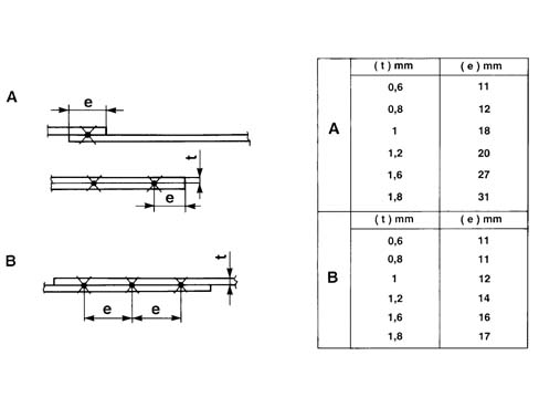
SPOT WELDING
Table of reference values for
carrying out spot welds.
A. Table for determining the distance of the spot welds from
the edges of the panels according to their thickness.
B. Table of reference values for the correct spacing of the spot
welds according to the thickness of the panel.
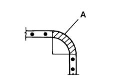
SPOT WELDING
. | Do not weld on angular shaped
surfaces. Welding on this type of surface would create a concentration
of tension which would result in breakage. |
Example of correct spot welding at corners.
A. Area where welding should not be carried out.
SEAM (MIG) WELDING
MIG welding should be used for parts
where spot welding cannot be used. When carrying out seam (MIG)
welding, check:
- the speed
- that the seam weld beads have been correctly made (alternating
weld sections)
In this welding system (automatic advance
seam) a protective inert gas atmosphere is used (hence the name
M.I.G. which stands for Metal Inert Gas). The continuous progress of the seam (which
constitutes both the electrode and the filler metal), allows long
welds to be made without interruption. The flow of inert gas sent to
the welding area eliminates the surrounding air preventing the oxidation
of the metal and therefore has the function of providing a protective
layer for the weld. For these reasons, MIG welding differs from
welding carried out with a covered electrode through the absence
of dross on the welding bead; also there are no pores which can occur
during normal arc welding. | The use of MIG welding requires
an extractor system to get rid of the fumes and harmful gases. |
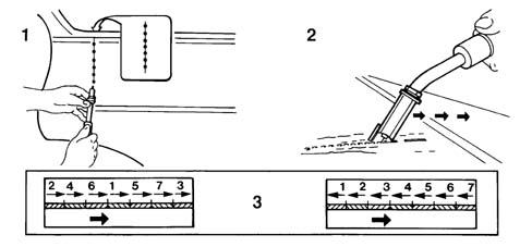
OPERATING METHODS
In order to weld two panels correctly
using a MIG welder: grind or pickle the panel thoroughly, place
the equipment in a sensible position so that whilst carrying out
the welding the outer casing of the torch does not become twisted
or assume positions which could hinder progress, wear protective
clothing and a suitable mask with non-actinic glass (glass standard
no. 8 for currents of 40/60A and no. 9 for currents of 80/200A).
Ensure good electrical contact. Regulate the flow of gas according
to the instructions of the equipment Manufacturer. Make two spot welds
at the two edges of the join line and one at the centre, then carry
out spot welds in the middle of the two sections defined in this
way. The spot welds should be 25-30 mm apart.The diagram below illustrates correct welding. | the correct gap is about 1 mm. |
Carrying out a weld using inert gas (MIG)
for joining two matched panels.
OPERATING METHODS
It is not advisable to initially
carry out a seam weld because, in addition to being difficult to
do, it can cause distortion of the panel through the accumulation
of heat involved.The difficulty in carrying out a weld with
a single bead lies in the need to move the torch fairly slowly in
order to achieve good weld penetration which is also quick enough not
to incur the risk of 'burning' the panel.Moving the torch too quickly also results
in a poor weld bead content because after the subsequent operations
of grinding the bead the layer of material remaining is not sufficient
to guarantee the resistance of the join.After the initial spot welding of the panel,
the spot welds should be ground to the level of the panel using
a rigid disc grinder.At this point the alignment of the panels
should be checked and, if necessary, corrected using a hammer and
steel dolly block.Then proceed with filling the gaps between
the various spot welds carrying out alternating welding sections, keeping
the torch at an angle of around 60°, (see diagram above).1. Tacking the join. The inset shows the
tack welds at the rear of the panel. Grinding join tack welds.2. Carrying out the welding.3. Two alternatives are illustrated for
the correct sequence of welding to be carried out to avoid deformations
of the panel.The fact that the weld has been carried
out correctly is confirmed from the rear of the weld bead which
should show a series of spherical bumps along the entire length
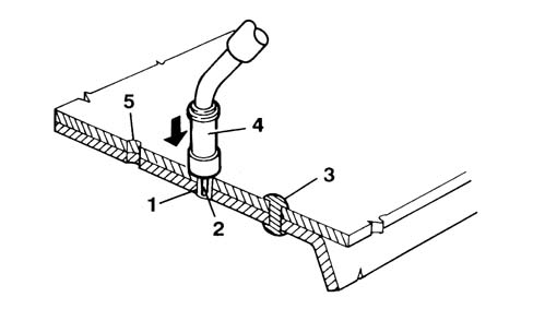
of the join.The MIG welder can also be used for joining
overlapping panels where only one side is accessible.To carry out the welding, the panels must
adhere perfectly and the torch should be kept perpendicular to the
surface.In this way the action of the electrode
melts the first panel initially, then the second producing a crater
which is filled.In order to carry out this operation correctly,
the welding machine must be adjusted to the correct current value
for the thickness of the panels being worked on and pressure must
be applied to the surface, with the torch resting on its supports,
to faciliate the matching of the panels.Where the thickness of the panels is more
than 1.5 - 2.5 mm, holes 0.6 mm in diameter must be made level with
the weld spots.Carrying out inert gas (MIG) welding to
join overlapping panels
1. Area where panels are joined
2. Electrode
3. Weld spot
4. Torch
5. Hole (only for thick panels)
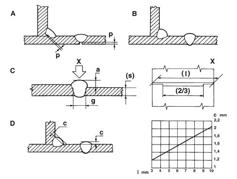
GENERAL INSTRUCTIONS FOR EXPOSED WELDING
Below are some important instructions
not be underestimated:
- the incomplete penetration (p) should be 15-30% of the
thickness of the panel (see diagram below
- point A incorrect welding, point B correct welding).
- the height of the bead (a) should be 60% of the thinnest
thickness (s), the clearance (g) between the panels before welding
should be 20% of the thinnest thickness for at least two thirds
of the length (l) of the bead, (see diagram below, point C and detail
X). The diagram indicates the value of the convexity (c) of the
bead according to the length (l) of the weld.
- the shape of the bead section should have a convexity (e)
which depends on the length of the actual bead (see diagram below,
point D).
Examples of welding.
BRAZING
Brazing is only used if the panels
being replaced have been welded by this method, with the welding
only carried out at the points defined by the Manufacturer. This type of welding does not guarantee
mechanical properties which are comparable with the other systems described
previously and therefore are not applicable for joining structural
parts. | When using oxyacetylene torches
for brazing, follow the safety instructions relating to their usage
and be sure to work in a safe environment. The use of this welding
system requires the use of an extractor system to get rid of the
fumes and harmful gases. |
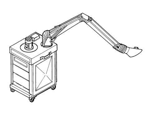
AIR FILTRATION AND PURIFICATION SYSTEM
When carrying out operations
which produce fumes, gases and dust which is dangerous to the operator,
air filtration and purification systems must be used.These systems are adapted to suit the varying
requirements and their size depends on the volume of air to be purified. These
systems usually operate through the combined action of mechanical
and electro-static filtration and purification through active charcoal.
The filtration takes place in two stages; mechanically eliminating
the largest particles of dust through wire gauze and then by subjecting
the air flow to ionization which statically charges the particles of
dust which will then be eliminated through the electro-static process.The air flow is then purified by passing
through active charcoal filters. In addition to their efficiency,
handling and noise levels in these systems has been improved so that
they never create a nuisance.The diagram below illustrates a possible
conformation decribed above.Example of a portable air filtration and
penetration system
Introduction
Painting the bodyshell has two
fundamental objectives; protecting the surfaces of the panels from
environmental attack and, from an aesthetic point of view, producing
a shiny, bright colour. The large number of chemical products used
in painting operations requires special care to be taken over their
handling and usage.These painting operations involve the emission
of paint fumes and solvent vapours which, if inhaled by the operators,
can seriously affect their health and they should only be carried
out in special spray booths.The operator should always wear a mask and
protective clothing.These masks can be the filtration type for
brief operations and the total protection pressurized type for longer
operations.
EQUIPMENT
The following equipment is used during
painting operations:
- filltration masks and protective clothing;
- masking materials and tape;
- spray booths and drying ovens;
- spray guns;
- infra-red lamps;
- polishers;
PROTECTIVE CLOTHING
When carrying out painting operations,
suitable clothing should always be worn, so that the operator is
well protected from contact with harmful agents.It is also advisable to use a barrier cream
applied to the most exposed uncovered areas (face, hands and arms) which
should be removed at the end of the painting operations. be removed
at the end of the painting operations.
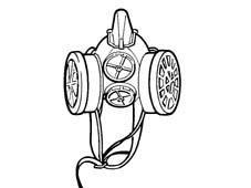
FILTRATION MASK
This type of mask only protects
the operator's respiratory tracts, so goggles and hair protection
should also be used at the same time. Its use is recommended for
small retouching operations.Example of a filtration mask.
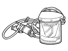
PRESSURIZED MASK
This mask guarantees protection
of both the face and hair and is supplied with pure air via the
compressed air system which operates the spray gun.The air is further purified with a degree
of separation approaching 100% by an active charcoal filter fitted
to the operator's belt.The slight excess pressure created inside
the helmet prevents the infiltration of paint vapours.The use of this mask is advisable for lengthy
painting operations. Example of a pressurized mask
SPRAY BOOTH
Painting and drying operations
for prepared parts should be carried out in spray booths. If the
extent of the damage repaired is medium to large, it is advisable
to use a special spray booth and a hot air oven for drying the paint.The workplace must be equipped with an air
conditoning system and filtered by purifiers, mainly consisting
of renewable active charcoal filters.The optimum painting conditions which
should be maintained in the booth during painting are as follows:
- constant temperature of between 22 -25 °?
- constant humidity of between 75-80%
The workplace in question can be:
- a combined type spray booth and drying oven;
- a separate type spray booth and drying oven.
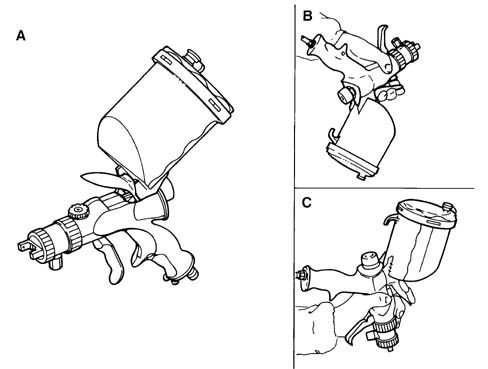
SPRAY GUNS
The development of ergonomics
and spraying techniques has led to the definition of a new type
high air volume and low atomization pressure spray gun where the
paint mist is considerably reduced. This type of spray gun is lighter with
a grip designed to reduce tiredness and the onset of cramp and has
a trigger which requires far less effort than traditional spray
guns. The handling of the spray gun has also been made easier through
the balance and the reduced visual restriction which allows greater
control when working. The most interesting aspect of this spray
gun is the supply system which allows painting in any direction, even
with the reservoir pointing downwards, also improving cleaning procedures
with a considerable saving in time and materials. The possibility
of painting from above or below in addition to preventing the formation
of areas which are either too wet or too dry, facilitates access to
areas of the bodywork which are difficult to reach. Special attention
has been paid to the ease of adjustment which requires minimal,
simple movements. This type of gun combines great efficiency with
a very refined atomization capacity for any produce, even those
which are water-soluble and is used at pressures of 0.7 g (10 PSI)
or less. Thanks to these capacities for exploiting the painting material,
considerable savings are achieved in financial terms and the working
environment is improved. The diagram below illustrates several possible
ways of using the gun.Using a spray gun
A. Normal method of use
SPRAY GUNS
B. Use from the bottom to the
topC. Use from the top to the bottom
PORTABLE INFRA-RED LAMPS
If the operation only involves
small retouches, the use of a drying oven is not advisable. In these
cases the paint can be dried using special infra-red lamps fitted
on parabolid mirrors. The use of one or more lamps positioned in
such a way that an even temperature is produced on the surface of
the area retouched, allows the drying of the paint film and produces
results which are comparable to those obtained in drying ovens.These types of lamps considerably reduce
the drying times, also reducing energy consumption. The lamp should
only be used when the paint has undergone a degree of drying so
that it is 'outside the powder' condition.Drying a retouched area using a portable
infra-red lamp
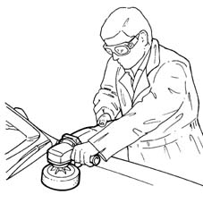
POLISHERS
The operation of polishing the
paint should only be carried out after drying the enamel and after
the base has cooled down to ambient temperature. Polishing is also necessary if there are
defects in the paintwork such as dust, paint fumes, drips, orange
peel, small scratches.There are many products designed to eliminate
these defects which should be applied either manually or mechanically,
using a polishing machine.The tool should be held parallel to the
surface to be polished and should not be held at an angle, to avoid
the paint overheating and the creation of circular, concentric grooves.The diagram below illustrates the correct
way of holding the polisher.Correct use of a polisher
Painting cycles
| When using chemical products,
follow the safety instructions from the supplier closely. |
The painting operations vary according to
the type of operation. The sequence of operations is described
in the paragraphs which follow. There is a special procedure for
the colour 'Nuvola (cloud) Light Blue'.
PAINTING A REPLACED BODY PANEL (BOLTED)
With the original part treated
with cataphoresis on electro-galvanized panels.1. Clean the replacement panel, to remove
any traces of dust, grease, etc. using a 'VOC' low volatile organic
compound detergent product.2. Carry out a slight 'surface' dry sanding
using P 220 - P 240 grade abrasive paper, using a power sander equipped with
a suction system only on the panel being painted.3. Suction the dust and clean with a low
'VOC' detergent product or an anti-silicone product.4. Apply a chrome-free passivating product
(wash primer) in a single coat to the areas stripped following the
instructions from the supplier.5. Apply sealant through extrusion to visible
panel joins/matches following the supplier's instructions (for the
subsequent application of the filler).6. Apply the high/medium solid filler, prepared
previously, following the supplier's instructions.7. Finish off with P 320 - P 400 grade abrasive
paper, dry sanding using power sanding machines fitted with a suction
system and repeat operation 3.8. Blow through the entire panel thoroughly.9. Clean the surface with an anti-static
cloth.10. Apply the pastel/metallic/metallescent
base tint, prepared previously, following the supplier's instructions.11. Apply the normal or high solid twin
component acrylic clear coat, prepared previously, following the
supplier's instructions. | Check the panel and, if there
is a slight dent, fill the part concerned with filler, then dry
sand it using P 320 - P 400 grade abrasive paper using a sanding
machine fitted with a suction system. Repeat operation 3/4. |
PAINTING A REPLACED BODY PANEL (WELDED)
With the original part treated
with cataphoresis on electro-galvanized panels.1. Clean the (welded) replacement panel
to eliminate any dust, grease, etc. using a low 'VOC' detergent
or an anti-silicone product.2. Dry sand the areas involved in the welding
with P 80 - P 120 grade abrasive paper using a sanding machine fitted with
a suction system.3. Carry out a slight 'surface' sanding
using P 220 - P 240 grade abrasive paper using a sanding machine
fitted with a suction system only on the panel involved in the painting.4. Suction the dust and clean with a low
'VOC' detergent product or an anti-silicone product.5. Apply a chrome-free passivating product
(epoxide base coat) to the stripped areas following the supplier's
instructions.6. Fill the join areas involved in the welding
with polyester filler, following the supplier's instructions.7. Dry sand with P 100 - P 120 grade abrasive
paper using a sanding machine fitted with a suction system and carry out
operation 4/5.8. Apply sealant through extrusion to visible
panel joins/matches following the supplier's instructions (for the
subsequent application of the filler).9. Apply the high/medium solid filler, prepared
previously, following the supplier's instructions.10. Finish with P 320 - P 400 grade abrasive
paper using a sanding machine fitted with a suction system and repeat operation
3.11. Clean the surface with an anti-static
cloth.12. Apply the pastel/metallic/metallescent
base tint, prepared previously, following the supplier's instructions.13. Apply the normal or high solid twin
component acrylic clear coat, prepared previously, following the
supplier's instructions. | Check the panel and, if there
is a slight dent, fill the part concerned with filler, then dry
sand it using P 320 - P 400 grade abrasive paper using a sanding
machine fitted with a suction system. Repeat operation 4/5. |
PAINTING A (REPAIRED) BODY PANEL
1. Dry sand the 'repaired area'
with P 80 - P 180 grade abrasive paper using a sanding machine fitted
with a suction system.2. Suction the dust and clean with a low
'VOC' detergent product or an anti-silicone product.3. Apply a chrome-free twin component passivating product
(epoxide base coat) to the repaired area in a single coat, following
the supplier's instructions.4. Fill the areas with air drying twin component
polyester filler.5. Dry sand with P 100 - P 120 grade abrasive
paper using a sanding machine fitted with a suction system and carry out
operation 2/3.6. Apply the high/medium solid filler by
shading in the filled area prepared previously, following the supplier's instructions.7. Dry sand with P 320 - P 400 grade abrasive
paper using a sanding machine fitted with a suction system and carry out
operation 2.8. Blow through the entire panel thoroughly.9. Clean the surface with an anti-static
cloth.10. Apply the pastel/metallic/metallescent
base tint, prepared previously, following the supplier's instructions.11. Apply the normal or high solid twin
component acrylic clear coat, prepared previously, following the
supplier's instructions. | Check the panel, if there is a
slight dent, fill the part concerned and then dry sand with P 320
- P 400 grade abrasive paper using a power sanding machine fitted
with a suction system. Repeat operation 2/3. |
PAINTING (REPLACEMENT) BUMPERS
1. Clean the bumper ordered from
the Parts Division to remove any traces of dust, grease, etc. using
an anti-static product because it is protected by a special base
coat for the subsequent painting.2. Rub down the surface to be painted, with
P 360 - P 400 grade abrasive paper, using a sanding machine fitted
with a suction system.3. Suction the dust and clean using a low
'VOC' anti-static product.4. Blow through the entire panel thoroughly.5. Clean the surface with an anti-static
cloth.6. Apply the chrome-free twin component
passivating product (plastic base coat) to all the stripped areas
in a single coat, following the supplier's instructions.7. Apply the pastel/metallic/metallescent
base tint, prepared previously, following the supplier's instructions.8. Apply the normal or high solid twin component
acrylic clear coat, prepared by the supplier. | Add elasticized clear coat, following
the supplier's instructions. |
PAINTING A PLASTIC(REPLACEMENT) ELEMENT (KMC COMPOUND
MATERIAL)
1. Clean the bolted (plastic)
part ordered from the Parts Division to remove any traces of dust,
grease, etc. using a low 'VOC' detergent product or an anti-silicone
product.2. Carry out a slight 'surface' dry sanding,
only on the plastic involved with the painting, with P 220 - P 240 grade
abrasive paper using a sanding machine fitted with a suction system. 3. Suction the dust and clean using a low
'VOC' detergent product.4. Apply high/medium solid filler, prepared
previously, following the supplier's instructions.5. Finish off with P 320 - P 400 grade abrasive
paper using a sanding machine fitted with a suction system. Repeat operation
3.6. Blow through the entire panel thoroughly.7. Clean the surface with an anti-static
cloth.8. Apply the pastel/metallic/metallescent
base tint, prepared previously, following the supplier's instructions.9. Apply the normal or high solid twin component
acrylic clear coat, prepared previously, following the supplier's instructions. | Check the panel and, if there
is a slight dent, fill the part concerned with filler, then dry
sand it using P 320 - P 400 grade abrasive paper using a sanding
machine fitted with a suction system. Repeat operation 3. |
PAINTING A NON REPLACED BODY PANEL/PLASTIC (KMC) ELEMENT
'COSMETIC CYCLE'
1 . Dry sand the panel with the
defect in the PV applied, with P 360 - P 400 grade abrasive paper,
using a sanding machine fitted with a suction system.2. Suction the dust and clean the panels
with low 'VOC' detergent or with an anti-silicone product, whilst
a low 'VOC' anti-static product should be used for plastics.3. Blow through the entire panel thoroughly.4. Clean the surface with an anti-static
cloth.5. Apply the pastel/metallic/metallescent
base tint, prepared previously, following the supplier's instructions.6. Apply the normal or high solid twin component
acrylic clear coat, prepared previously, following the supplier's instructions.
PAINTING REPLACEMENT OF REPAIRED PANELS USING SPECIAL
'NUVOLA' MICALIZED ENAMEL
'Nuvola' micalized enamel is
a special colour with a CHANGING/PEARLESCENT appearance. The iridescent
effect is achieved through a special enamel containing particles
of mica coated in iridescent colourings; this type of enamel is
an almost transparent paint which adds a pearlescent appearance
to the base colour which shows through and gives the tone.
PAINTING A REPLACEMENT PANEL (WITH THE ORIGINAL PART
TREATED WITH CATAPHORESIS)
Operating cycle for 'Nuvola'
micalized enamel with iridescent colourings. 1. Clean the replacement panel to remove
any traces of dust, grease, etc. using low 'VOC' detergents.2. If there is accidental rust due to storage,
grind the area until the panel is stripped.3. Slightly dry sand the 'surface' of only
the part of the panel involved in the painting, using 220 grade
abrasive paper using a sanding machine fitted with a suction system.4. Clean the exposed part of the panel using
a low 'VOC' detergent. 5. Blow through the entire panel with compressed
air. 6. Apply the chrome-free twin component
passivating product by spraying in a single coat. (film thickness
from 5 -10 micron).7 . Apply plastic sealants to the joins
where applied originally (see specific cycle in Notes chapter).8. Apply High Solid twin component filler,
by spraying in two cross coats, with an interval of several minutes according
to the desired thickness.9. Wait for 10 - 15 minutes before starting
the drying.10 . Dry the primer in an oven at a temperature
of 40°....60° ? f?? 30 - 40 minutes. (Film thickness from 70....80
micron; hardness F-H).11. Dry sand the element sprayed with suction
using 400 grade abrasive paper. Make sure that the element is at ambient
temperature for this operation.12. Blow with compressed air.13. Clean with low 'VOC' detergents and
polish with an anti-static cloth.14. Apply a cross coat of twin layer pastel
enamel.15. Dry for 10-15 minutes at ambient temperature
(20°?) and then dry in an oven at a temperature of (60°?) for
40 minutes.16. Dry sand the element sprayed with suction
using 800 grade abrasive paper. Make sure that the element is at ambient
temperature for this operation.17. Blow with compressed air.18. Clean with low 'VOC' detergents and
polish with an anti-static cloth.19. Apply the 'Nuvovla' base coat by spraying
one light coat and four normal coats at intervals of several minutes then
follow with a light, faded-in coat to even the paint (film thickness
around 30 micron).20. Drying for 15-20 minutes at a temperature
of 20°C. - 21. Application of normal or high solid twin component acrylic
clear coat.22. For normal clear coat: spray a light
coat followed by two coats at intervals of several minutes. 23. For High Solid clear coat: spray a light
coat followed by another coat with an interval of several minutes. 24. Dry for 15......20 minutes at ambient
temperature (20°?) and then dry in an oven at a temperature of
60°C for 40 minutes (film thickness 40....50 micron; hardness HB-F).25. Possible mechanical or manual polishing
of the retouch or the painted panel (or the adjacent area) with
fine grade abrasive paste and/or polish. | It is advisable to carry out this
operation at least 24 hours after drying. |
PAINTING A REPAIRED - RETOUCHED PANEL (OPERATION
ON BARE PANEL)
Operating cycle for 'Nuvola'
micalized enamel with iridescent colourings.1. Sand the area to be retouched using 150
- 220 grade abrasive paper taking care to level the surrounding
area and eliminate any traces of corrosion on the exposed panel.2. Clean the exposed part of the panel and
the surrounding area overhauled with low 'VOC' detergent.3. Blow through with compressed air.4. Apply the chrome-free twin component
passivating product to the exposed areas of the panel by spraying
in a single coat. (Film thickness from 5 - 10 micron).5. Possible filling with air drying twin
component polyester product.6. Dry overhauling with suction of the area
filled with 80 - 120 grade abrasive paper.7. Blow through with compressed air.8. Wash the sanded area with low 'VOC'
detergents.9. Further application of the twin component
passivating product on the areas of the panel exposed during sanding by
spraying a single coat.10. Application of High Solid twin component
filler by spraying 2....4 cross coats, with intervals of several
minutes according to the desired thickness.11. Wait for 10 - 15 minutes before starting
the drying.12. Drying of base coat with infra-red lamps.13. Initial distance 50 - 60 cm. for a period
of 5 minutes; then place the lamp 35 - 40 cm away for 15 minutes.
(Film thickness from 80 to 150 microns). hardness F-H). Alternatively,
dry in an oven at a temperature of 60°C for 40 minutes.14. Dry sand the element sprayed with suction
using 400 grade abrasive paper. Make sure that the element is at ambient
temperature for this operation.15. Blow with compressed air.16. Clean with low 'VOC' detergent.17. Polish with an anti-static cloth.18. Carry out the cycle for replacement
panels from point 1.12 to point 1.20.
PAINTING THERMO-PLASTIC MATERIAL COMPONENTS (OPERATIONS
ON REPLACEMENT PARTS)
On the model in question, these
parts are the: Bumper, Miniskirts.Operating cycle for 'Nuvola' micalized enamel
with iridescent colourings.1. Apply the adhesion promoter (primer)
for thermo-plastic materials.2. Carry out the cycle for replacement panels
from point 1.12 to point 1.20.
PAINTING THERMO-HARDENING MATERIAL COMPONENTS (OPERATIONS
ON REPLACEMENT PARTS)
On the model in question, the
part involved is the fuel filler. Operating cycle for 'Nuvola' micalized enamel
with iridescent colourings. 1. Carry out the cycle for replacement panels
from point 1.7 to point 1.20. | All the operations of sprying
the passivating product, the filler and the enamels should be carried
out in a spray booth after having masked the area surrounding the
component involved. Base coats, filler, enamels and solvents should be
handled and used in well ventilated areas. Special solvents with
a maximum of 3% toluene and xylene should be used for cleaning the equipment.
Before carrying out any polishing, make sure that the panel and
he surrounding area are at ambient temperature. Before spot welding
panels, apply electro-weldable galvanizing protective (PPG D 386
- 459632 or an equivalent product) to the ground edges of the join
area. |
Renewing the anti-corrosion treatments, sound insulation
and sealants.
The treatments to which the bodyshell
is subjected to achieve the necessary resistance characteristics
to corrosion, sound insulation and sealing can be damaged or destroyed
by repair operations.They should therefore be renewed, as appropriate
during the repair operations, so that the vehicle is restored to
its original condition.
EQUIPMENT
The following equipment is used:
- power guns for sealant product extrusion;
- foam injection systems;
- wax based oil injection systems;
In box sections which have been replaced
or repaired by welding or overheating, the internal anti-corrosion
protection must be renewed through:
- the application of rust converter in the overheated
or welded areas which require drying for at least 24 hours at ambient
temperature (20 °C);
- the application of wax based protection in the replaced or
repaired box section (type PPG 853.764 or equivalent product);
- Renew the rigid type expanded polyurethane foam in the
box sections (e.g.: Schiuma - fix from BOSTON, Schiumal P.U.R. from
TORGGLER - Merano or an equivalent product);
- Where necessary, restore the sealing of the joins;
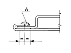
- Carry out the sealing, following the instructions given below,
in the flanges of the moving parts (tailgates, lids) supplied as
spares; on a replaced component treated with cataphoresis, clean
the areas involved with heptane or anti-silicon/anti-static solvents;
- Apply a bead of SIKAFLEX 221 type polyurethane sealant
manufactured by SIKA (*) in the shape and position illustrated in
the diagram;
- Leave the sealant to dry for 24 hours at ambient temperature
(20 °C) or 40 minutes at 60 °C; - Carry out the normal painting
of the component. Apply sound-deadening paint on external parts
which have been replaced or repaired, as required.
(*) Alternatively, use a similar product
manufactured by 3M or other equivalent products, following the supplier's instructions.Example of application of sealant
A. Sealant
EQUIPMENT
| When using chemicals, closely
follow the safety instructions given on the safety sheet which the supplier
must give to the user. |