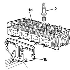
2429749 - 1016E10 single cylinder head, removed - overhaul
 | Name | Country |
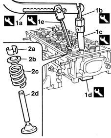
|---|---|---|
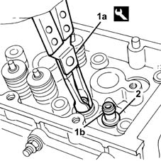
| 1b | Support | 1.860.470.000 |
| Name | Country |
|---|---|---|
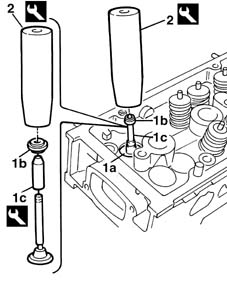
| 1a | Lever | 1.860.790.000 |
| Name | Country |
|---|---|---|
| 1b | Lever hook | 1.860.788.000 |
| Name | Country |
|---|---|---|
| 1c | Extension | 1.860.787.000 |
| Name | Country |
|---|---|---|
| 1d | Valve retaining base | 1.860.786.000 |
| Name | Country |
|---|---|---|
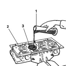
| 1e | Chamber | 1.860.877.000 |
| Name | Country |
|---|---|---|
| 1a | Extractor | 1.860.989.000 |
 | Measurement | Value | |
|---|---|---|---|
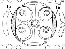
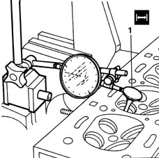
| - | Flatness of bottom surface (mm) | 0.1 |
| Measurement | Value | |
|---|---|---|---|
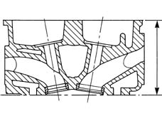
| - | Cylinder head height (construction figure) (mm) | 77 ± 0.2 |
| Measurement | Value | |
|---|---|---|---|
| - | Combustion chamber volume (cm) | 12.28 |
| Measurement | Value | |
|---|---|---|---|
| - | Inlet and exhaust valve stem diameter (mm) | 5.90 ÷ 5.94 |
| Measurement | Value | |
|---|---|---|---|
| - | Valve cylindrical section thickness (mm) | 1 |
| Measurement | Value | |
|---|---|---|---|
| - | Exhaust and inlet valve outer diameter (mm) | 22.55 ÷ 27.05 |
| Measurement | Value | |
|---|---|---|---|
| - | Valve guide inner diameter (mm) | 6.022 - 6.040 |
| Measurement | Value | |
|---|---|---|---|
| - | Valve stem - valve guide clearance (mm) | 0.14 ÷ 0.082 |
| Measurement | Value | |
|---|---|---|---|
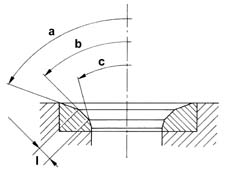
| - | Upper section taper "" (-) | 45° ± 20' |
| Measurement | Value | |
|---|---|---|---|
| - | Contact band with valve taper "b" (-) | 30° |
| Measurement | Value | |
|---|---|---|---|
| - | Lower band taper"c" (-) | 15° |
| Measurement | Value | |
|---|---|---|---|
| - | Contact band width with valve "I" (mm) | ~ 2 |
| Measurement | Value | |
|---|---|---|---|
| - | Spring height (mm) | 33.6 | |
| Under load (daNm) | 16.7 | ||
| Measurement | Value | |
|---|---|---|---|
| - | Spring height (mm) | 25.2 | |
| Under load (daN) | 36.6 | ||
| Name | Country |
|---|---|---|
| 1c | Drift | 1.860.993.000 |
| Name | Country |
|---|---|---|
| 2 | Drift | 1.860.993.000 |
| Name | Country |
|---|---|---|
| - | Lever | 1.860.790.000 |
| Name | Country |
|---|---|---|
| - | Lever hook | 1.860.788.000 |
| Name | Country |
|---|---|---|
| - | Extension | 1.860.787.000 |
| Name | Country |
|---|---|---|
| - | Valve retaining base | 1.860.786.000 |
| Name | Country |
|---|---|---|
| - | Chamber | 1.860.877.000 |
| Name | Country |
|---|---|---|
| - | Support | 1.860.470.000 |