2429754 - 1024A10 crank shaft - r + r with engine removed - check main and connecting rod bearingand replace if necessary
 | Name | Country |
|---|---|---|
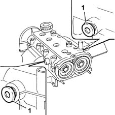
| 1 | Counter-torque | 1.860.846.000 |
| Name | Country |
|---|---|---|
| 1 | Counter-torque | 1.870.763.000 |
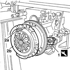
| Work with flywheel retainer 1860846000 fitted. |
| Name | Country |
|---|---|---|
| 1 | Flange | 1.860.815.000 |
| Name | Country |
|---|---|---|
| - | Flange | 1.860.815.000 |
 | Measurement | Value | |
|---|---|---|---|
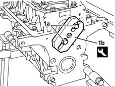
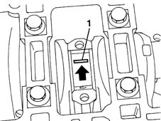
| 1 | End float (mm) | 0.055 ÷ 0.265 |
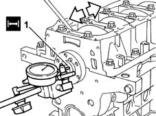
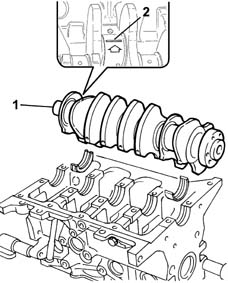
| The central main bearing halves incorporate crankshaft thrust half-rings. |
| Measurement | Value | |
|---|---|---|---|
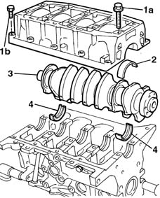
| - | Main bearing journal diameter (mm) | Category B | 47.988 ÷ 47.994 |
| Category C | 47.982 ÷ 47.988 | ||
| Class A | 47.997 ÷ 48.003 | ||
| The shaft has undergone a nitriding treatment; therefore if it needs regrinding it should undergo the nitriding treatment again and the dimensions should then be checked. |
| Measurement | Value | |
|---|---|---|---|
| - | Main bearing journal undersize (mm) | 0.127 |
| Measurement | Value | |
|---|---|---|---|
| - | Crankpin diameter (mm) | 41.990 ÷ 42.008 |
| The shaft has undergone a nitriding treatment; therefore if it needs regrinding it should undergo the nitriding treatment again and the dimensions should then be checked. |
| Measurement | Value | |
|---|---|---|---|
| - | Crankpin undersize (mm) | 0.127 |
| Name | Country |
|---|---|---|
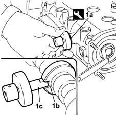
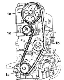
| 1c | Protractor | 1.860.942.000 |
 | Fastening | Component | Ø | Value(daNm) |
|---|---|---|---|---|
| - | Bolt | CRANK CASE | M10 x 1.25 | 2 + 90° |
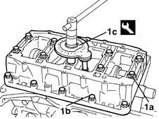
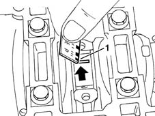
| Check one pin at a time without turning the crankshaft. |
| Measurement | Value | |
|---|---|---|---|
| - | Clearance between crankshaft bearings and main journals (mm) | 0.025 ÷ 0.040 |
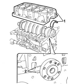
| Apply a 2 mm thick, unbroken sealant strip to the lower crankcase surface. |
 | Type | Component | Name | Qty. |
|---|---|---|---|---|
| - | Silicon sealant | LOWER CRANKCASE | LOCTITE 5900 | 2 mm |
| Name | Country |
|---|---|---|
| - | Flange | 1.860.815.000 |
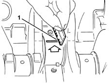
| The letters for the cylinder bore/liner class are located on the cylinder block/crankcase. |
| Name | Country |
|---|---|---|
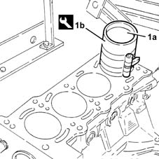
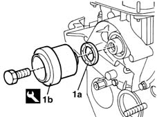
| 1b | Fitting tool | 1.860.700.000 |
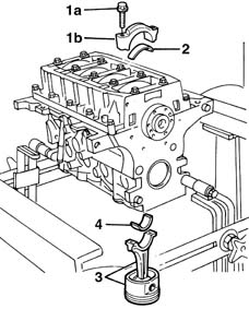
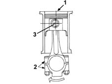
| The connecting rods come with split caps. if replaced, they are supplied pre-split by the manufacturer. Check that the components are free of burrs, blisters, scratches or any type of surface defect. Before installation, the parts must be thoroughly washed, cleaned and dried. The connecting rod caps are fitted so that the number stamped on them is facing the same side as the one stamped on the big end (inlet side). |
| Each connecting rod must be matched with its own cap, respecting the printed reference numbers. connecting rods and connecting rod caps are not interchangeable. |
| Fastening | Component | Ø | Value(daNm) |
|---|---|---|---|---|
| 1c | Bolt | CONNECTING ROD CAP FASTENERS | M8 | 2 + 40° |
| Name | Country |
|---|---|---|
| 1d | Protractor | 1.860.942.000 |
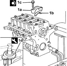
| Check the one connecting rod pin at a time without rotating the crankshaft. |
| Measurement | Value | |
|---|---|---|---|
| - | Big end bearings (mm) | 0.024 - 0.060 |
| Name | Country |
|---|---|---|
| - | Flange | 1.860.815.000 |
| Fastening | Component | Ø | Value(daNm) |
|---|---|---|---|---|
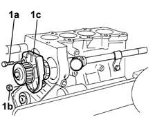
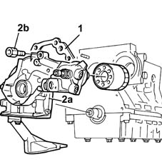
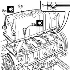
| 2b | Bolt | ENGINE OIL PUMP | M6 x 20 | 1 |
| Fastening | Component | Ø | Value(daNm) |
|---|---|---|---|---|
| 2b | Bolt | ENGINE OIL PUMP | M6 x 32 | 1 |
| Name | Country |
|---|---|---|
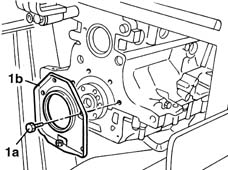
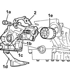
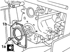
| 1b | Fitting tool | 1.860.990.000 |
| The rear crankcase cover comes with an oil seal. |
| Fastening | Component | Ø | Value(daNm) |
|---|---|---|---|---|
| 1b | Bolt | FLYWHEEL SIDE COVER | M6 x 20 | 1 |
| Fastening | Component | Ø | Value(daNm) |
|---|---|---|---|---|
| 1b | Bolt | FLYWHEEL SIDE COVER | M6 x 32 | 1 |
| Name | Country |
|---|---|---|
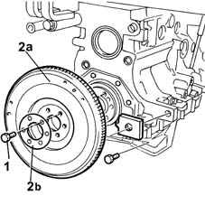
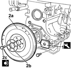
| 1 | Counter-torque | 1.860.846.000 |
| Fastening | Component | Ø | Value(daNm) |
|---|---|---|---|---|
| 2c | Bolt | FLYWHEEL | M8 | 4.4 |
| Name | Country |
|---|---|---|
| 2 | Counter-torque | 1.870.763.000 |
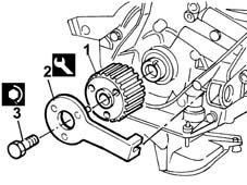
| Work with the flywheel retainer 1860846000 fitted. |
| Fastening | Component | Ø | Value(daNm) |
|---|---|---|---|---|
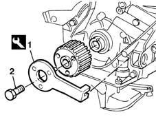
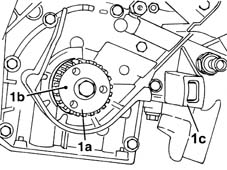
| 3 | Bolt | TOOTHED DRIVE PULLEY | M12 x 1.25 | 2 + 90° |
| Ensure a perfect join between start and end section. |
| Type | Component | Name | Qty. |
|---|---|---|---|---|
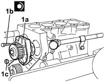
| - | Silicon sealant | COOLANT PUMP | - | - |
| Fastening | Component | Ø | Value(daNm) |
|---|---|---|---|---|
| 1b | Bolt | COOLANT PUMP | M6 | 1 |
| Fastening | Component | Ø | Value(daNm) |
|---|---|---|---|---|
| 1c | Nut | COOLANT PUMP | M6 | 1 |
| Name | Country |
|---|---|---|
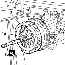
| 1b | Clutch centering | 1.870.418.000 |
| Ensure a perfect join between start and end section. |
| Type | Component | Name | Qty. |
|---|---|---|---|---|
| 1 | Silicon sealant | OIL SUMP | LOCTITE 5900 | - |
| When fitting the crankcase sump, avoid major sideways movements which may remove the sealant. |
| Fastening | Component | Ø | Value(daNm) |
|---|---|---|---|---|
| 2b | Bolt | OIL SUMP | M6 | 1 |
| Fastening | Component | Ø | Value(daNm) |
|---|---|---|---|---|
| 2c | Nut | OIL SUMP | M6 | 0.5 |
| Name | Country |
|---|---|---|
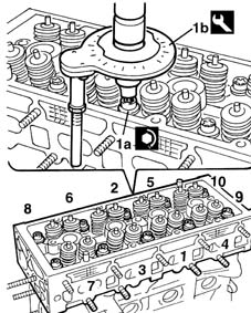
| 1a | Locating pin | 1.860.985.000 |
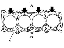
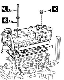
| The cylinder head gasket is metallic. |
| Follow the order shown in the diagram for each tightening sequence. |
| Fastening | Component | Ø | Value(daNm) |
|---|---|---|---|---|
| 1a | Bolt | CYLINDER HEAD | M9 x 1.25 | 3 + 90° + 90° |
| Name | Country |
|---|---|---|
| 1b | Protractor | 1.860.942.000 |
| Name | Country |
|---|---|---|
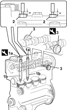
| 2 | Tappet retaining tool | 1.860.988.000 |
| Name | Country |
|---|---|---|
| 3a | Key | 1.860.834.000 |
| Fastening | Component | Ø | Value(daNm) |
|---|---|---|---|---|
| 3b | Bolt | CYLINDER HEAD EXTENSION | M8 x 1 | 1.5 |
| Fastening | Component | Ø | Value(daNm) |
|---|---|---|---|---|
| 4 | Bolt | CAMSHAFT HOUSING PLUGS | M16 x 1 | 1.5 |
| The pistons were already approximately aligned previously. |
| The camshafts were timed previously through the fitting of the tools (3). |
| Name | Country |
|---|---|---|
| 1a | Bearings | 1.860.992.000 |
| Name | Country |
|---|---|---|
| 3 | Locating pin | 1.860.985.000 |
| Make sure that this operation is carried out with the camshaft pulley (1c) slack. |
| Name | Country |
|---|---|---|
| 1a | Support for counter-torque | 1.860.831.000 |
| Name | Country |
|---|---|---|
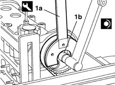
| 1a | Spanner for camshaft pulley rotation | 1.860.831.002 |
| Fastening | Component | Ø | Value(daNm) |
|---|---|---|---|---|
| 1b | Bolt | TIMING GEAR DRIVEN PULLEYS | M12 x 1.25 | 12 |
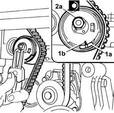
| Fastening | Component | Ø | Value(daNm) |
|---|---|---|---|---|
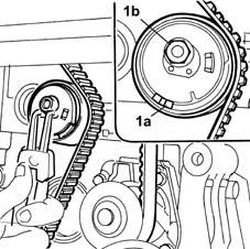
| 2a | Nut | MOBILE TIMING TENSIONER | M8 | 2.5 |
| Fastening | Component | Ø | Value(daNm) |
|---|---|---|---|---|
| - | Bolt | CAMSHAFT HOUSING SIDE PLUGS | M16 x 1.5 | 1.5 |
| Fastening | Component | Ø | Value(daNm) |
|---|---|---|---|---|
| - | Bolt | CRANKSHAFT PULLEY | M8 | 2.2 |
 | Name | Connector |
|---|---|---|
| - | Integrated throttle body actuator | N75 |
| Name | Connector |
|---|---|---|
| - | Fuel vapour recovery solenoid | L10 |
| Name | Connector |
|---|---|---|
| - | Engine temperature sender unit | K36 |
| Name | Connector |
|---|---|---|
| - | Injector junction | D81 |
| Name | Connector |
|---|---|---|
| - | Earth on engine | C40 |
| Name | Connector |
|---|---|---|
| - | Detonation sensor | K50 |
| Name | Connector |
|---|---|---|
| - | Integrated air temperature sensor | K43 |
| Name | Connector |
|---|---|---|
| - | Engine oil pressure sensor (switch) | K30 |
| Name | Connector |
|---|---|---|
| - | Rpm sensor | K46 |