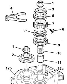
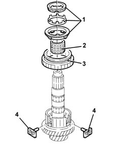
2429772 - 2110B20 manual gearbox (5 speed) with differential - dismantle and rebuild - wash and check parts - replace synchronisers and internal controls if necessary
 | Name | Country |
|---|---|---|
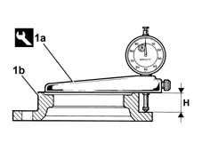
| - | Gearbox mount | 1.860.873.000 |
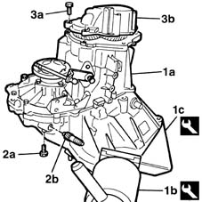
| Two operators are needed for this operation. |
| Name | Country |
|---|---|---|
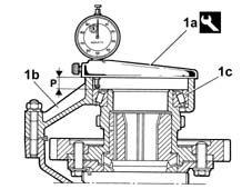
| 1b | Rotating stand | 1.871.000.000 |
| Name | Country |
|---|---|---|
| 1c | Support | 1.871.001.014 |
| Name | Country |
|---|---|---|
| 1b | Brackets | 1.840.005.308 |
| Name | Country |
|---|---|---|
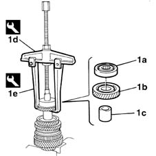
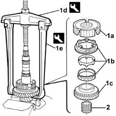
| 1c | Extractor | 1.840.005.001 |
| Name | Country |
|---|---|---|
| 1d | Counter weight | 1.840.206.000 |
| The simultaneous engagement of two gears will cause the gearbox shafts to lock. |
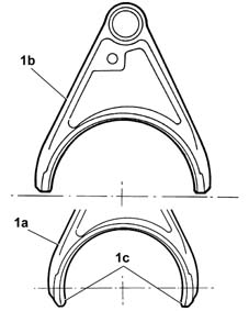
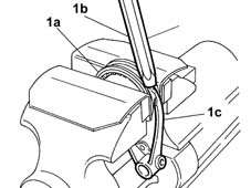
| Positioning the selector fork for 5 th speed in neutral is necessary to prevent the synchronizer rollers from being lost. |
| Starting from the month of June 1998, a new selector fork for engaging 5 th speed has been adopted on C510-C513 type gearboxes which replaces the selector fork fitted previously. The new selector fork (no. 46549946) should be fitted on gearboxes where it is already used (production from 6/98), but it is interchangeable with the previous selector fork (fitted on gearboxes produced before 6/98). The previous selector fork (which should only be fitted on gearboxes produced before 6/98) is available from the Parts Division until stocks run out. |
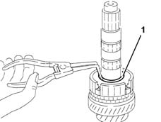
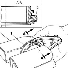
| take care not to damage the tapered part of the sleeve and the ends of the selector fork with the drift. |
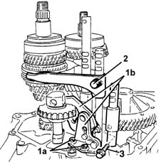
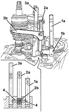
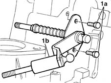
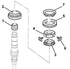
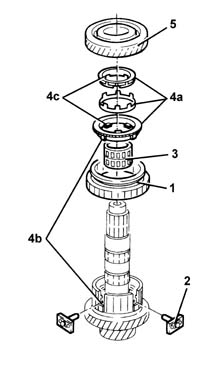
| If the rod offers resistance to being withdrawn, move the other rods (2a) and (3a) to shift the pawls (4) and (2b). |
| Work carefully to avoid the pawl (2b) accidentally falling out. |
| Name | Country |
|---|---|---|
| 1d | Extractor | 1.840.005.002 |
| Name | Country |
|---|---|---|
| 1e | Clamps | 1.840.005.303 |
| Name | Country |
|---|---|---|
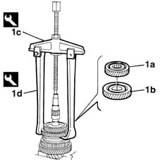
| 1c | Extractor | 1.840.005.002 |
| Name | Country |
|---|---|---|
| 1d | Clamps | 1.840.005.306 |
| When refitting, replace the circplip. |
| Name | Country |
|---|---|---|
| 1d | Extractor | 1.840.005.002 |
| Name | Country |
|---|---|---|
| 1e | Clamps | 1.840.005.306 |
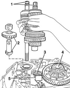
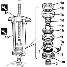
| The layshaft front bearing inner race should not be refaced; if necessary, replace it together with the layshaft. |
| Name | Country |
|---|---|---|
| 1n | Extractor | 1.840.005.002 |
| Name | Country |
|---|---|---|
| 1o | Clamps | 1.840.005.306 |
| Name | Country |
|---|---|---|
| 1b | Fitting tool | 1.860.945.000 |
| Name | Country |
|---|---|---|
| 1b | Fitting tool | 1.860.945.000 |
| Name | Country |
|---|---|---|
| 1b | Fitting tool | 1.860.945.000 |
| Name | Country |
|---|---|---|
| 1b | Fitting tool | 1.870.465.000 |
| Name | Country |
|---|---|---|
| 2b | Fitting tool | 1.870.465.000 |
| Name | Country |
|---|---|---|
| 1b | Drift | 1.870.448.000 |
 | Fastening | Component | Ø | Value(daNm) |
|---|---|---|---|---|
| 1b | Bolt | GEAR ENGAGMENT SELECTOR LEVER | M8 | 2.1 - 2.6 |

| Name | Country |
|---|---|---|
| 1b | Fitting tool | 1.875.016.000 |
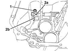
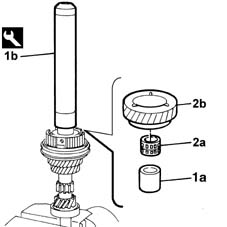
| Make sure that the gear engagement teeth are facing downwards. |
| Position the safety pawl in the rod before fitting it in the housing. |
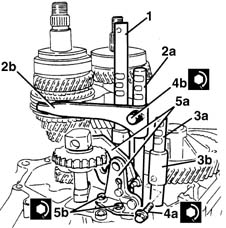
| To facilitate the fitting, move the 1 st - 2 nd speed selector forks (5a) in the direction shown by the arrow. |
| Fastening | Component | Ø | Value(daNm) |
|---|---|---|---|---|
| 4a | Bolt | 1st - 2nd speed selector fork | M6 | 1.5 - 1.9 |
| Fastening | Component | Ø | Value(daNm) |
|---|---|---|---|---|
| 4b | Bolt | 3rd - 4th speed selector fork | M6 | 1.5 - 1.9 |
| Fastening | Component | Ø | Value(daNm) |
|---|---|---|---|---|
| 5b | Bolt | Reverse selector fork mounting bracket | M6 | 8.5 - 1.1 |
 | Type | Component | Name | Qty. |
|---|---|---|---|---|
| - | Sealant | GEARBOX SEALS/GASKETS | Loctite 573 | - |
| Keep the gear selector/engagement lever upwards and check that the gear selector engages with the 3 rd - 4 th speed selector fork. |
| Fastening | Component | Ø | Value(daNm) |
|---|---|---|---|---|
| - | Bolt | GEARBOX GEAR CASING | M8 | 2.1 - 2.6 |
| Fastening | Component | Ø | Value(daNm) |
|---|---|---|---|---|
| - | Bolt | REVERSE IDLER | M8 | 2.9 - 3.6 |
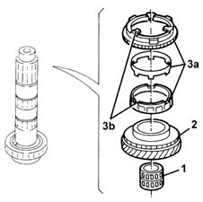
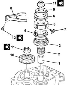
| To facilitate the fitting of the circlips, place them with their openings at the front. |
| Type | Component | Name | Qty. |
|---|---|---|---|---|
| - | Sealant | GEARBOX SEALS/GASKETS | Loctite 573 | - |
| Fastening | Component | Ø | Value(daNm) |
|---|---|---|---|---|
| - | Bolt | GEARBOX REAR COVER SPACER | M8 | 2.1 - 2.6 |
| Fastening | Component | Ø | Value(daNm) |
|---|---|---|---|---|
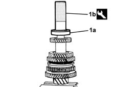
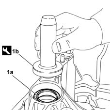
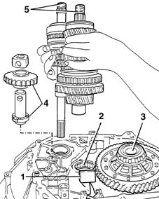
| 11 | Ring nut | GEAR SHAFTS | M20 | 10 - 12.4 |
| Fastening | Component | Ø | Value(daNm) |
|---|---|---|---|---|
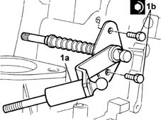
| 12 | Bolt | GEARBOX INTERNAL CONTROLS | M6 | 1.5 - 1.9 |
| When the fitting is complete, check that the sleeve can rotate freely inside the selector fork. |
| Type | Component | Name | Qty. |
|---|---|---|---|---|
| - | Sealant | GEARBOX SEALS/GASKETS | Loctite 573 | - |
| Fastening | Component | Ø | Value(daNm) |
|---|---|---|---|---|
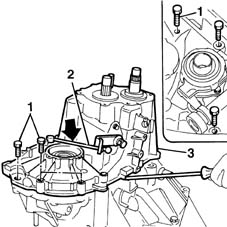
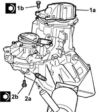
| 1b | Bolt | GEARBOX REAR COVER | M8 | 2.1 ÷ 2.6 |
| Name | Country |
|---|---|---|
| 1a | Support | 1.895.655.000 |
| Name | Country |
|---|---|---|
| 1a | Support | 1.895.655.000 |
| Name | Country |
|---|---|---|
| 1a | Support | 1.895.655.000 |
| Name | Country |
|---|---|---|
| 1a | Support | 1.895.655.000 |
| 0.12 corresponds to the interference for bedding in and the pre-loading of the differential bearings. After having determined the exact value of the scraper ring, try and achieve the closest possible value to that obtained using the rings available as spares. If the value obtained does not correspond to the thickness of one or more adjustment shims available, fit the shim(s) giving the closest value which is immediately higher. |
| Name | Country |
|---|---|---|
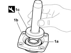
| 1c | Fitting tool | 1.875.016.000 |
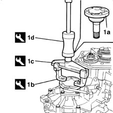
| Two operators are needed for this operation. |
| Name | Country |
|---|---|---|
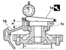
| 1c | Support | 1.871.001.014 |
| Name | Country |
|---|---|---|
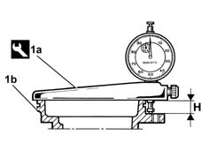
| - | Gearbox mount | 1.860.873.000 |