2429777 - 2110D10 differential inner case - r + r with manual gearbox removed - includes gearbox dismantle and rebuild
 | Name | Country |
|---|---|---|
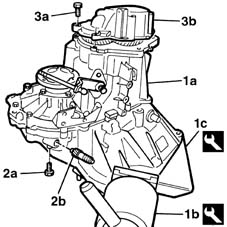
| - | Gearbox mount | 1.860.873.000 |
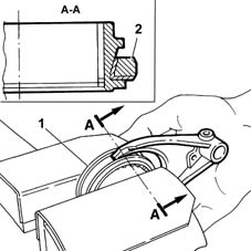
| Two operators are needed for this operation. |
| Name | Country |
|---|---|---|
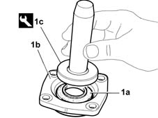
| 1b | Rotating stand | 1.871.000.000 |
| Name | Country |
|---|---|---|
| 1c | Support | 1.871.001.014 |
| Name | Country |
|---|---|---|
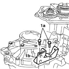
| 1b | Brackets | 1.840.005.308 |
| Name | Country |
|---|---|---|
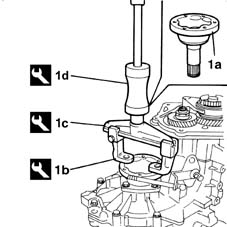
| 1c | Extractor | 1.840.005.001 |
| Name | Country |
|---|---|---|
| 1d | Counter weight | 1.840.206.000 |
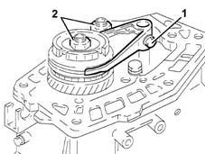
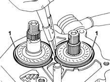
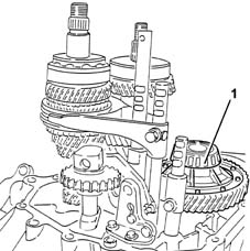
| The simultaneous engagement of two gears will cause the gearbox shafts to lock. |
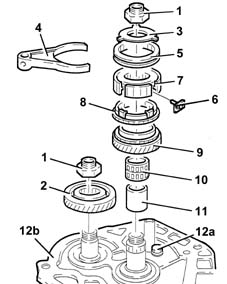
| Positioning the selector fork for 5th speed in neutral is necessary to prevent losing the synchronizer rollers. |
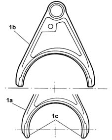
| Starting from the month of June 1998, a new selector fork for engaging 5th speed has been adopted on C510-C513 type gearboxes which replaces the selector fork fitted previously. The new selector fork (no. 46549946) should be fitted on gearboxes where it is already used (production from 6/98), but it is interchangeable with the previous selector fork (fitted on gearboxes produced before 6/98). The previous selector fork (which should only be fitted on gearboxes produced before 6/98) is available from the Parts Division until stocks run out. |
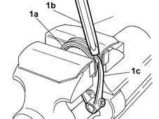
| take care not to damage the tapered part of the sleeve and the ends of the selector fork with the drift. |

 | Fastening | Component | Ø | Value(daNm) |
|---|---|---|---|---|
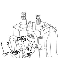
| 11 | Ring nut | GEAR SHAFTS | M20 | 10 - 12.4 |
| Fastening | Component | Ø | Value(daNm) |
|---|---|---|---|---|
| 12 | Bolt | GEARBOX INTERNAL CONTROLS | M6 | 1.5 - 1.9 |
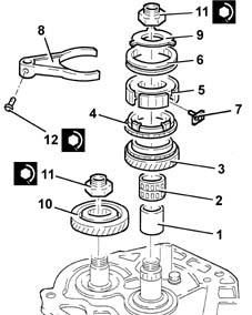
| When it is fitted, check that the sleeve can rotate freely inside the selector fork. |
 | Type | Component | Name | Qty. |
|---|---|---|---|---|
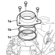
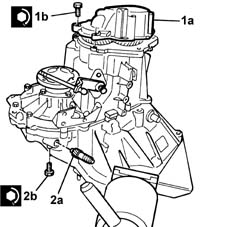
| - | Sealant | GEARBOX SEALS/GASKETS | Loctite 573 | - |
| Fastening | Component | Ø | Value(daNm) |
|---|---|---|---|---|
| 1b | Bolt | GEARBOX REAR COVER | M8 | 2.1 ÷ 2.6 |
| Name | Country |
|---|---|---|
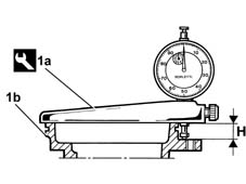
| 1a | Support | 1.895.655.000 |
| Name | Country |
|---|---|---|
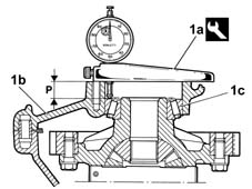
| 1a | Support | 1.895.655.000 |
| Name | Country |
|---|---|---|
| 1a | Support | 1.895.655.000 |
| Name | Country |
|---|---|---|
| 1a | Support | 1.895.655.000 |
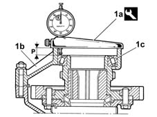
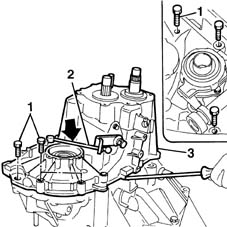
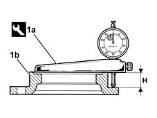
| 0.12 corresponds to the interference for bedding in and the pre-loading of the differential bearings. After having determined the exact value of the scraper ring, try and achieve the closest possible value to that obtained using the rings available as spares. If the value obtained does not correspond to the thickness of one or more adjustment shims available, fit the shim(s) giving the closest value which is immediately higher. |
| Name | Country |
|---|---|---|
| 1c | Fitting tool | 1.875.016.000 |
| Two operators are needed for this operation. |
| Name | Country |
|---|---|---|
| 1c | Support | 1.871.001.014 |
| Name | Country |
|---|---|---|
| - | Gearbox mount | 1.860.873.000 |