3232879 - 1060G pressure pump electric control
COMPONENT DESCRIPTION
Injection control unit (EDC-15C Common Rail)
It is fitted to the right side of the engine
bay. The control unit is the 'flash EPROM' type, i.e. reprogrammable from
the outside without intervening on the hardware.The injection control unit integrates the
absolute pressure sensor.PIN-OUT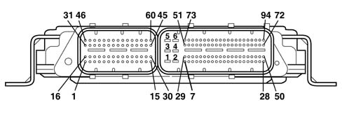
RPM SENSOR
Specifcations
It is fitted on the cylinder block/crankcase
and 'faces' the flywheel on the crankshaft.It is of the inductive type, i.e. it functions
by means of the variation in the magnetic field generated by the passage
of the teeth of the flywheel (60-2 teeth).The fuel injection control unit uses
the rpm sensor to:
- determine the rotation speed;
- determine the angle of the crankshaft.
Operation
The passage from full to empty, due to the
presence or absence of the tooth, causes a variation in the magnetic flow
which is sufficient to generate an induced alternating voltage,
resulting from the count of teeth located on a ring (or phonic wheel).The frequency and range of the voltage sent
to the electronic control unit provides it with the angular speed of
the crankshaft.
1 - Brass bush
2 - Permanent magnet
3 - Plastic sensor casing
4 - Coil winding
5 - Polar core
6 - Ring gear or flywheel
7 - Coaxial two-wire cable or electrical connection
The distance (gap) for obtaining correct
signals, between the end of the sensor and the flywheel, should
be between 0.8 and 1.5 mm.This gap is not adjustable, so if a value
outside the tolerance range is measured, check the condition of
the sensor and the flywheel.
1 - Maximum magnetic flow
2 - Minimum magnetic flow
3 - Induced alternating voltage trend
CAM ANGLE SENSOR
Specifcations
Hall effect; it is mounted on the cylinder
head and 'facing' the camshaft pulley.This pulley comprises a tooth which enables
the timing sensor to indicate the engine's timing position.The fuel injection control unit uses the
timing sensor's signal to find out the TDC at the end of compression.Operation
A semiconducting layer, through which current
passes, immersed in a perpendicular magnetic field (force lines perpendicular
to the current direction), generates at its ends a difference in
potential known as Hall voltage.If the intensity of the current remains
constant, the voltage generated only depends on the intensity of
the magnetic field; the intensity of the field simply has to vary
periodically to produce a modulated electrical signal, whose frequency
is proportional to the speed with which it changes magnetic field.
To obtain this change, a tooth on the inside of the pulley moves
close to the sensor.
1 - Earth
2 - Signal
3 - Supply
INTAKE AIR TEMPERATURE AND EXCESS PRESSURE SENSOR
Specifcations
The intake air temperature and excess pressure
sensor is a component which is designed to measure the pressure
and the temperature of the air inside the inlet manifold.It is fitted on the intake manifold
has the task of notifying the injection control unit to:
- regulate the pressure of the variable geometry turbine
in order to ensure optimum engine performance in all operating conditions.
- regulating injection duration.
1 - Earth
2 - Air temperature signal
3 - 5 Volt (from ECU)
4 - Supercharging pressure output signal
ENIGINE COOLANT TEMPERATURE SENSOR
Specifcations
It is fitted on the thermostatic cup and
measures the temperature of the coolant by means of an NTC thermistor which
has a negative resistance coefficient.One NTC thermistor sends the signal to the
injection control unit whilst the other one sends the signal to
the temperature gauge and warning light in the instrument panel.The sensor is based on semiconductor technology;
so if the sensor temperature increases as the water temperature
increases, the resistance decreases.As the variation in resistance is not linear,
for the same temperature increment, it is higher for low temperatures than
for high temperatures.AIR FLOW METER WITH AIR TEMPERATURE SENSOR INTEGRATED
Specifcations
The flow meter is located on the air inlet
duct and is of the 'hot film' type.
1 - Air temperature sensor output signal
2 - Maintenance current
3 - Negative
4 - 5V supply
5 - Flow meter output signal
The intake air temperature sensor is built
into the flow meter. | The air flow meter cannot be dismantled. |
Operation
The operating principle is based on a heated
diaphragm located in a measuring duct through which the intake air
entering the engine flows.The hot film diaphragm is kept at a constant
temperature (about 120° C above the incoming air temperature) by
the heating coils.The air mass passing through the measuring
duct tends to draw heat from the diaphragm, so to keep the latter at
a constant temperature, some current must flow through the resistor.This current is measured by a suitable Wheatstone
bridge.The current is therefore proportional to
the mass of flowing air. | The flow meter directly measures
the air mass (not volume), thus eliminating problems of temperature,
altitude, pressure, etc. |
Fuel temperature sensor
Specifications
It is built into the fuel heater and measures
the temperature of the coolant by means of an NTC thermistor which
has a negative resistance coefficient.The sensor is based on semiconductor technology;
so if the sensor temperature increases as the fuel temperature increases,
the resistance decreases.As the variation in resistance is not linear,
for the same temperature increment, it is higher for low temperatures than
for high temperatures.FUEL PRESSURE SENSOR
Specifcations
It is fitted at the end of the 'rail'
fuel distribution manifold and has the task of supplying the injection
control unit with a 'feedback' signal to:
- regulate the injection pressure
- regulating injection duration.
1 - Earth
2 - Output signal
3 - Supply
ACCELERATOR PEDAL POTENTIOMETER
Construction features
The sensor consists of a casing, secured
to the accelerator pedal mount, which contains a shaft, in an axial position,
connected to two potentiometers: one main one and one safety one.There is a coil spring on the shaft which
guarantees the correct resistance to the pressure whilst a second spring
ensures the return on release.Operation
The position of the accelerator pedal is
transformed into an electrical voltage signal and is sent to the
fuel injection control unit by the potentiometer connected to the
accelerator pedal.The accelerator pedal position signal is
processed together with the information relating to the rpm, to
obtain the fuel injection times and relevant pressure.


