3232973 - 5580E anti-theft device
The vehicle is fitted as standard with an ALFA ROMEO CODE immobilizer system to protect against theft.An antitheft system with volumetric protection and an alarm is available on request.ALFA ROMEO CODE
To increase protection against theft attempts, the vehicles have bee fitted with an electronic engine immobilizer system known as the 'ALFA ROMEO CODE'.The keys are equipped with an electronic transponder which transmits a coded signal to a special electronic control unit. If it recognizes the code sent, it allows the engine to be started up.New design system with cipher code
The second generation Code system has the same operating logic as the previous system already used on all Group vehicles, with the exception of the following variants:
- the code used in the dialogue, which takes place via the aerial, between the Code control unit and the key varies each time the engine is started up ('ROLLING CODE') and is in cipher: therefore the code cannot be reproduced, even with an electronic scanner
- Master key eliminated: two keys which have already been 'programmed' for both the Code system and the alarm (remote control), if fitted, are supplied
- Code control unit with direct autodiagnosis
- programming of codes in a DATA BASE managed by PARTS DEPT. Therefore when the new vehicle is handed over to the customer, the service network should not carry out any programming procedure for the Code or the alarm.
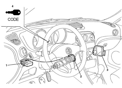
Code system components
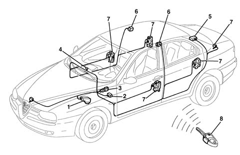
The Code system consists of:
- two (or more) electronic keys
- a Code electronic control unit, with a serial line for communication with the engine control unit
- aerial in the ignition switch
- CODE Card for the emergency starting procedure.
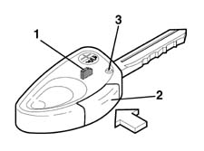
Keys
2 keys are supplied, with transponder and remote control (if an alarm is fitted).The transponder is an electronic device, NOT supplied by the battery, which contains a special 'ID' code (different for each key and not in cipher) and the secret code connected to the vehicle Code control unit.When the key is inserted in the ignition, in the ON position, the transponder is energized by radio waves from the aerial around the key lock barrel and automatically responds by emitting a code.The remote control contains a specific code (see DESCRIPTION AND OPERATION: Alarm).| The keys are supplied already programmed by the production plant. |
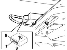
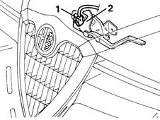
Code control unit
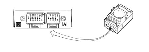
The main function of the Code control unit is to recognize the key inserted in the ignition switch.The Code control unit is also responsible for programming the keys and the Code warning light.The Code control unit contains the secret code used in the dialogue which takes place via the aerial between the Code control unit and the key transponder.It also contains the codes for the enabled keys (IK1 and ID2) and the fix code (non-cryptic code used in the dialogue between the Code control unit and the engine control unit: when the key is turned to the ON position for the first time, if the key is recognized, the FIX CODE is transferred to the engine control unit).The Code control unit has a direct diagnostic line, independent from the engine control unit line.The Code control unit and the engine control unit 'converse' via a serial line with a single cable.The serial line is the two-way type: this means that the information travels in a sequential fashion from the engine control unit to the Code control unit and viceversa.Code control unit pin-outRefer to the illustration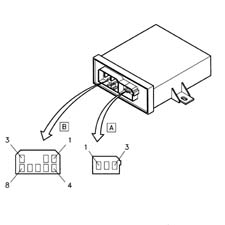
Dialogue between the code control unit, key and engine control unit
- With the ignition key in the ON position, the engine control unit asks the Code control unit for the FIX CODE- The Code control unit asks the transponder in the key for ID- The transponder transmits ID1 to the Code control unit where the ID received is compared with the enabled ones- If the ID received is amongst the enabled ones, the secret code is checked through a coded dialogue between the Code control unit and the transponder- If this recognition takes place, the Code control unit sends the FIX CODE to the engine control unit, which checks that it conforms and enables the starting and running of the engine. The Code warning light goes outIf this recognition does NOT take place, the Code control unit sends a special code to the engine control unit which does not allow the engine to be started up. The Code warning light remains on constantly.The logic of the dialogue between the two control units is summarized in the diagram.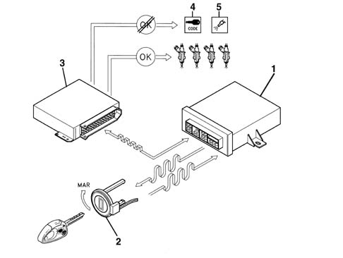
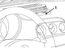
Code system warning light
The Code warning light in the instrument panel is managed by the Code control unit.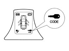
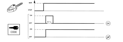
If the ignition key is turned to the ON position, the indicator can signal one of the following conditions:
- on briefly (0.7 s) and then off: key recognized, system operation correct;
- on constantly: the control unit has detected one of the following faults:
- key not recognized by the Code control unit;
- serial line between Code control unit and engine control unit not connected or no communication between the control units
- key programming procedure not carried out (new control unit from PARTS DEPT.).
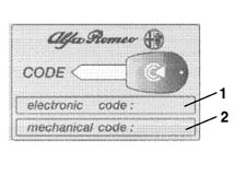
Code card
This is the card which contains:
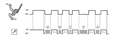
- the emergency electronic code which allows the vehicle to be started using the Examiner or other diagnostic instrument or, in an emergency, using the accelerator pedal
- the mechanical code.
| The Code Card should not be left in the vehicle in case it is stolen: it should, however, be available for the emergency starting procedure described below. |
System self-test
The control unit carries out a continuous self-test of the system's operation. In particular:
- it detects and memorizes any faults
- it recognizes the various components and the type of fault
- it signals the onset of these faults via the special warning light in the instrument panel.
The control unit provides information on:
- the state of the control unit: it indicates whether the control unit is correctly programmed and operational, if it is unusable, or if the 'Key Programming' procedure has not been carried out (new control unit ordered from PARTS DEPT.)
- the state of the Code warning light: on or off (it makes it possible to identify any irregularities in the warning light connections)
- the status of the key (correctly programmed or not)
The control unit then recognizes faults in all the system components:
- Code control unit
- aerial
- key transponder;
- serial line with engine control unit.
It is also possible to carry out the following procedures using the Examiner:
- Key programming
| Any keys no longer present are automatically and definitively cancelled in a new programming. |
| After an emergency starting procedure, if the ignition is turned to the OFF position, the engine control unit will return to the engine immobilized condition and the procedure should be repeated, if necessary. |
Data base
There is a centralized DATA BASE (for all markets) managed by the PARTS DEPT. for ordering all system components.The production plant transfers all the details needed into this DATA BASE together with the chassis number of the new vehicle.This PARTS DATA BASE should be used by the Service Network for ordering replacement components.The DATA BASE contains various information, including:
- vehicle chassis number
- ID1, ID2, (up to a maximum of 8)
- PASSWORD
- mechanical key code
| (*) For versions with an alarm, there are special codes for the remote controls for each key: a remote control cannot be recreated with the same code as the one lost. |
Intervention procedures
Loss of key(s)1. Ask the customer for all the keys remaining in his possession. He should also prove that he owns the vehicle by showing the registration document and a valid identity document.2. Carry of the PROGRAMMING OF THE KEYS remaining using the Examiner or other diagnostic equipment working on the Code control unit. In this way ke| ... DATA ERROR - CROPPED TEXT | Ошибка данных - Текст обрезан ... |
|---|
ALARMS
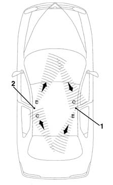
The alarm system offers volumetric and perimeer protection for the vehicle.An electronic control unit monitors the following:
- the closure state of the doors and lids (perimeter control)
- the presence of a moving object inside the passenger compartment (volumetric control)
- the operation of the ignition switch
- the condition of the supply cables for the vehicle and the emergency key.
| The radiofrequency type of remote control adopted facilitates the activation operations because this system has a high capacity, which is non directional and not affected by the transparency and cleanliness of the windows.In addition, the system for transmitting the secret code between the remote control and the receiver is a rolling code, in other words a cipher code which is different each time. |
System components
The alarm system consists of:
- two (or more) keys with remote control
- an electronic control unit with a built in siren
- a remote control receiver
- Volumetric sensors
- an LED (device activated indicator)
- an emergency key (not planned for certain markets)
- a bonnet opening switch (incorporated in the lock)
- a boot opening switch (incorporated in the lock)
- a doors open switch (incoroprated in the locks).
| The keys are supplied by the production plant already programmed. All the codes are then stored in a DATA BASE managed by the Parts Department. Therefore when a new vehicle is handed over to a customer, the Service Network should not carry out any programming procedure.If one of the keys is mislaid or there is a request for additional keys, then this request should be passed on to the Parts Division according to the following procedure. |

The main function of the control unit is to check:
- the state of the doors and the lids, through the switches in the locks
- the presence of a moving object inside the passenger compartment, via volumetric sensors.
- the condition of the system supply cables (both directly from the battery and those controlled by the ignition)
- the condition of the supply cables for the emergency key (if fitted)
- the operation of ignition switch
It is connected to the control unit via the serial line and directly manages the following system functions:
- it receives, decodes and manages the remote control signals
- it locks and unlocks the doors
- it memorizes the codes for enabled transmitters.
| Each receiver is programmed by the production planT. All the codes are then stored in a DATA BASE managed by the Parts Division. Therefore when a new vehicle is handed over to a customer, the Service Network should not carry out any programming procedure. If a receiver is being replaced, the request should be forwarded to the Parts Division following the procedures described below. |
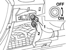
It makes it possible to exclude the system, for example in the case of repair operations:
- by turning the key in an anti-clockwise direction, the system is deactivated: emergency key in OFF position
- by turning the key in a clockwise direction, the system is activated: emergency key in ON position.
System operation
Switching onit is only possible to switch on the alarm with the ignition key in the OFF or PARK positions or with it extracted.The alarm is activated by pressing the button in the remote control. It has an operating range of about 10 metres.When the command has been given, the door locks are locked, the siren sounds and, at the same time, the direction indicators come on for about 2.5 seconds; the deterrent LED also flashes. the deterrent LED also flashes.| the activation of the auditory signals and the flashing of the direction indicators depends on the various country modes (see description which follows). |
| the activation of the auditory signals and the flashing of the direction indicators depends on the various country modes, as described later on. |
The system can be deactivated with the emergency key (OFF position) if:
- the remote control batteries are run down
- the system is faulty
- the vehicle is not used for long periods (more than 3 weeks).
| ... DATA ERROR - CROPPED TEXT | Ошибка данных - Текст обрезан ... |
|---|