3239232 - Introduction - INSTRUMENT PANEL
GLOSSARY
LCD
Liquid Crystal Display This consists of elements where, after the electric current passes through, the transparency is altered, composing figures or letters according to the basic electrical circuit.The gauges and warning lights on the instrument panel are clustered into four different modules.
- speedometer
- revs counter
- fault display
- central module

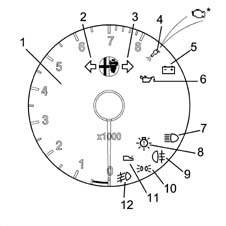
SPEEDOMETER
The module includes
- electronic speedometer
- mileometer and trip counter
- outdoor temperature gauge
- warning lights

| If the battery is disconnected, the trip meter is zeroed. |
External temperature (in ° C) can be displayed instead of mileage by adopting the following procedure:
- press the button for longer than 2 seconds to reset the trip counter
- press the button for less than 2 seconds to display outdoor temperature
- if outdoor temperature is lower than + 3 ° C, the system automatically switches to the temperature display, which flashes and shows an ice symbol to indicate the danger of an icy road surface. This message remains for 10 seconds and is repeated after 20 seconds.
| Because an outdoor temperature signal is not produced (in versions with heater), the temperature is not shown on the outdoor temperature display. |
Resetting mileage
The total mileage counter can be reset only once - during the first 200 km - following handling during production or prior to delivery to the Customer. In the case of a new instrument, the mileage reading is preceded by an 'F' (e.g. 'F00199'). After 200 km, the letter F disappears automatically and the reading becomes '000201'.If the reset button is pressed for longer than 10 seconds before 200 km, the letter H disappears and the counting restarts from '000000'. This operation can only be carried out once!Warning lights
The following warning lights are present on the speedometer:
- seat belt
| In a version available in some markets, the warning light goes off when the driver's seat belt has been done up. |
Warning light test
The module internal electronic circuits also manage a warning light test function for all modules: upon start-up (key turned on), all the warning lights and leds are turned on for about 4 seconds to check they are workingIn the case of the mileometer (LCD), all the lcd segments are turned on for about 4 seconds to check they are working.Replacing bulbs
Two bulbs on the back of the module light the module itself, and another lights the display. These bulbs can be replaced by unscrewing the bulb holder.
Speedometer module pin-out
Refer to the illustration
REV COUNTER
The module includes:
- electronic rev counter
- warning lights
Warning lights
- left turn signals
- right turn signals
- recharging
- minimum oil pressure
- injection system failure
when the ignition is switched on, the warning light comes on, controlled by the engine management control unit, for about 4 seconds as a self-test; if no faults are found, it goes out after this period. On the EOBD versions, the system conducts a continuous diagnosis of the components relating to emissions and indicates to the user, by the specific warning light on the instrument coming on, the following conditions of deterioration:
- malfunction of the catalytic converter, which does not convert the pollutants produced by the engine;
- malfunction of the Lambda sensors (oxygen sensors);
- lack of combustion ('misfire'), so unburnt fuel reaches the catalyzer which is damaged by chemical reactions which result in a rapid increase in temperature.
| Prompt repair of the problem which has caused the warning light to come on is vital in accordance with the legal requirements of the traffic regulations of the country in question. For further details Characteristic of working principle 1056 PETROL INJECTION SYSTEM . |
| The warning light is AMBER on the 'EOBD' versions, while it is still red on versions which only detect 'injection system fault'. |
- light failure (check)
Exterior lighting check
The rev counter module contains an exterior lighting check.The following circuits are checked by electronic components (microrelays):
- side lights
- number plate lights
- rear fog lamps
- brake lights (not 3rd brake light).
The following faults are detected:
- blown bulb
- bulb s.c. to earth or positive
- incorrect bulb (5W bulb instead of 21W)
Replacing bulbs
two bulbs on the back of the module are used to light the module itself. These bulbs can be replaced by unscrewing the bulb holder.The main beam warning light bulb can also be replaced.
Rev counter module pin-out
Refer to the illustration
REV COUNTER (Selespeed only)
The module includes:
- electronic rev counter
- warning lights
- SELESPEED display

| ... DATA ERROR - CROPPED TEXT | Ошибка данных - Текст обрезан ... |
|---|
CONSTRUCTION FEATURES
The gauges and warning lights on the instrument panel are clustered into four different modules.
- speedometer
- rev counter
- fault display
- central module
- infocenter module

| This version describes the instrument configuration adopted in the specifications without the VDC option. Versions with VDC are covered by a separate description. |
speedometer
The module includes
- electronic speedometer
- milometer and trip meter
- warning lights

| If the battery is disconnected, the trip meter is zeroed. |
Resetting mileage
The total mileage counter can be reset only once - during the first 200 km - following handling during production or prior to delivery to the Customer.In the case of a new instrument, the mileage reading is preceded by an 'F' (e.g. 'F00199'). After 200 km, the letter F disappears automatically and the reading becomes '000201'.If the reset button is pressed for longer than 10 seconds before 200 km, the letter H disappears and the counting restarts from '000000'. This operation can only be carried out once!Warning lights
The following warning lights are present on the speedometer.Brake pad wear warning lightDuring starting, when the ignition is turned on, the warning light comes on as a self-test, then goes out.Eobd warning light (for both petrol and jtd engines, starting from september 03)The AMBER warning light is activated by the engine control unit for about 4 seconds (check) at the Key On.The EOBD (European On Board Diagnosis) system carries out continuous diagnosis of the car's petrol fuel system components relating to emissions and indicates any deterioration of these components by the warning light in the instrument panel coming on.The aim of the system is:
- keeping the efficiency of the system under control;
- signalling an increase in emissions due to a vehicle malfunction;
- signalling the need to replace deteriorated components.
| Prompt repair of the problem which has caused the warning light to come on is vital in accordance with the legal requirements of the traffic regulations of the country in question. For further details Characteristic of working principle 1056 PETROL INJECTION SYSTEM or Characteristic of working principle 1060 DIESEL FUEL INJECTION |
Warning light test
The module internal electronic circuits also manage a warning light test function for all modules: upon start-up (key turned on), all the warning lights and leds are turned on for about 4 seconds to check they are workingIn the case of the mileometer (LCD), all the lcd segments are turned on for about 4 seconds to check they are working.Replacing bulbs
Two bulbs on the back of the module light the module itself, and another lights the display. These bulbs can be replaced by unscrewing the bulbl holder.
Speedometer module pin-out
Refer to the illustration.
| PIN | SIGNAL |
|---|---|
| 1 | Earth |
| 2 | Seat belts warning light input |
| 3 | Brake fluid/handbrake on signal for check |
| 4 | Panel warning lights autotest operation |
| 5 | Engine oil sensor + |
| 6 | Passenger Air Bag disabled warning light |
| 7 | Brake fluid/handbrake signal input |
| 8 | INFOCENTER serial |
| 9 | Battery + |
| 10 | Ignition + |
| 11 | Speedometer signal from ABS |
| 12 | Panel lighting adjustment |
| 13 | Engine oil sensor - |
| 14 | Rep. speedometer |
| 15 | Rep. Speedometer |
| 16 | Instant consumptioin |
| PIN | SIGNAL |
|---|---|
| 1 | EOBD failure |
| 2 | Fuel level gauge control |
| 3 | Left front door |
| 4 | Rev counter lighting adjustment |
| 5 | Side/parking lights on control |
| 6 | Instrument lighting adjustment button |
| 7 | Reserve warning light control |
| 8 | Engine rpm |
| 9 | Fuel level gauge |
| 10 | Fuel level gauge |
| 11 | Brake pad wear |
| 12 | Trip meter zeroing button |
revs counter
The module includes
- electronic rev counter
- warning lights

Warning lights
The following warning lights are present on the rev counter:
- left turn signals
- right turn signals
- lights failure (check); when the ignition it turned on, the warning light comes on for about 4 seconds as a self-test.
- main beam headlamps
- side lights/dipped beams
- rear fog lamps
- fog lights
- trailer lights (predisposition)
Exterior lighting check
The rev counter module contains an exterior lighting check.The following circuits are checked by electronic components (microrelays):
- side lights
- number plate lights
- rear fog lamps
- brake lights (not 3rd brake light).
The following faults are detected:
- blown bulb
- bulb s.c. to earth or positive
- incorrect bulb (5W bulb instead of 21W)
Replacing bulbs
Two bulbs on the back of the module are used to light the module itself. These bulbs can be replaced by unscrewing the bulbl holder.The main beam warning light bulb can also be replaced.
Automatic transmission failure warning light
The red warning light located in the rev counter comes on in the case of faults or critical driving conditions (e.g. transmission fluid overheating).During starting, when the ignition is turned on, the warning light comes on for about 4 seconds as a self-test, then goes out to show the system is working properly.If the warning light begins to flash and stays on, the automatic transmission management system is faulty.If the warning light stays on with a fixed light, or if it comes on with a fixed light during driving, the transmission fluid is overheating.Replacing bulbs
Two bulbs on the back of the module are used to light the module itself. These bulbs can be replaced by unscrewing the bulbl holder.The main beam warning light bulb can also be replaced.
Rev counter module pin-out
Refer to the illustration.
| PIN | SIGNAL |
|---|---|
| 1 | right rear side light |
| 2 | left front side light |
| 3 | side lights signal |
| 4 | left rear fog lamp |
| 5 | stop lights signal |
| 6 | trailer side light |
| 7 | trailer fog lamp |
| 8 | dipped beam enablement |
| 9 | left rear side light |
| 10 | direct power supply for check |
| 11 | left number plate light |
| 12 | right number plate light |
| 13 | right brake light |
| 14 | earth |
| 15 | supply controlled by the ignition |
| 16 | direct power supply for check |
| 17 | right rear fog lamp |
| 18 | left brake light |
| 19 | brake light for trailer |
| 20 | right front side light |
| PIN | SIGNAL |
|---|---|
| 1 | rear fog lamps signal |
| 2 | trailer turn signal warning light |
| 3 | rev counter module lighting |
| 4 | main beam warning light |
| 5 | heater plugs warning light |
| 6 | engine rpm signal input |
| 7 | water in diesel filter warning light |
| 8 | engine rpm signal output |
| 9 | left direction indicators warning light |
| 10 | engine rpm repetition |
| 11 | N.C. |
| 12 | serial line for Q-System/Selespeed gearbox |
| 13 | Q-System/Selespeed gearbox buzzer |
| 14 | fog lamp warning light |
| 15 | engine rpm repetition |
| 16 | right trailer direction indicators warning light |
FAULT DISPLAY
The module includes the following warning lights.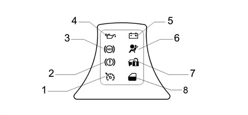
Air bag failure warning light
When the ignition is turned on, the warning light comes on, controlled by the relevant control unit, for about 4 seconds as a self-test; if no faults are found, it goes out after that period. Characteristic of working principle 5580C air bag systemThe warning light also comes on in the case of a faulty connection or if the circuit conecting warning light and control unit is short circuited to earth. The warning light is 'smart', i.e. its inner control circuit checks that the connection is correct.Code failure warning light
The warning light comes on upon a command from the Code control unit for 1 second when the ignition is turned, then it goes off to indicate that the key has been recognised and the system is efficient (see ) Characteristic of working principle 5580E anti-theft deviceAbs failure warning light When the ignition is turned on, the warning light comes on, controlled by the ABS control unit, for about 4 seconds as a self-test; if no faults are found, it goes out after that period. Characteristic of working principle 3340 A(B.S. ANTI-LOCK BRAKING SYSTEM .)The warning light also comes on in the case of a faulty connection or if the circuit conecting warning light and control unit is short circuited to earth. The warning light is 'smart', i.e. its inner control circuit checks that the connection is correct.Low brake fluid level and handbrake warning lightWhen the ignition is turned on, the warning light comes on, controlled by the ABS control unit, for about 2 seconds as a self-test; if no faults are found, it goes out after that period. If it comes on, during driving, together with the ABS failure warning light, it indicates a fault in the EBD braking system. Characteristic of working principle 3340 A(B.S. ANTI-LOCK BRAKING SYSTEM .)If it comes on by itself, the brake fluid level is low or the handbrake is on.Door open warning light
The warning light is only present on versions without INFOCENTER.
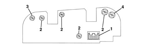
Fault display pin-out
Refer to the illustration.
| PIN | SIGNAL |
|---|---|
| 1 | CODE failure warning light |
| 2 | Earth |
| 3 | Cruise Control warning light |
| 4 | Low brake fluid/handbrake engaged signal |
| 5 | Earth |
| 6 | Door open warning light |
| 7 | Recharging warning light |
| 8 | ABS warning light |
| 9 | Air bag failure warning light |
| 10 | Earth |
| 11 | EBD signal from ABS |
| 12 | Earth |
| 13 | Supply controlled by the ignition |
| 14 | Earth |
| 15 | Min. engine oil pressure repetition |
| 16 | Min. oil pressure warning light |
central module
The module includes
- fuel gauge, with reserve warning light
- engine coolant temperature gauge, with maximum temperature warning light
- analogue clock

Fuel refilling should not take place in the following two circumstances:
|
Replacing bulbs
Four bulbs on the back of the module are used to light the module. These bulbs can be replaced by unscrewing the bulbl holder.The following two warning light bulbs can also be changed;
- fuel reserve
- maximum coolant temperature warning light
Central module pin-out
Refer to the illustration.
| relay | Supply controlled by the ignition |
|---|---|
| relay | Direct supply |
| 3 | Earth |
| 4 | Fuel level gauge (-) |
| 5 | Fuel level gauge (+) |
| 6 | Central module warning light test |
| 7 | Central module lighting |
| 8 | Rep. coolant temperature signal |
| 9 | maximum coolant temperature warning light |
| 10 | Engine coolant temperature gauge |
| 11 | Fuel level signal for engine management control unit |
| 12 | Rep. coolant temperature signal |
Infocenter module
This is an ISTN, negative transreflective type display: the visible area is divided as illustrated in the diagram
| ... DATA ERROR - CROPPED TEXT | Ошибка данных - Текст обрезан ... |
|---|