3239194 - Introduction - ENGINE
GLOSSARY
GLOSSARY
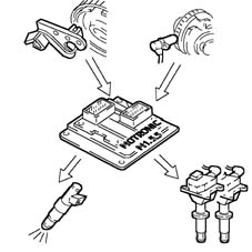
Engine with 4 cylinders in line, double ignition, 16 valves, 1598 cc, twin overhead cam, electrohydraulic timing variator, with Bosch Motronic M2.10.4 integrated electronic fuel injection-ignition.Description
General characteristics
The unit comprises the engine and all the systems required for its operation:
- fuel supply system
- air supply system
- engine cooling system
- exhaust system with catalytic converter
- fuel vapour recirculation system.
The Bosch Motronic M2.10.4 system belongs to the category of integrated systems:
- inductive discharge digital electronic ignition
- static distribution
- sequential phased electronic fuel injection (1 - 3 - 4 - 2).
During idling, the control unit checks:
- the moment of ignition
- the air flow
System functions are essentially as follows:
- adjustment of fuel injection times
- adjustment of ignition advance values
- check on cold starting
- check on enrichment during acceleration
- fuel cut-off during overrunning
- check and management of idle speed
- limitation of maximum rpm
- check on combustion - Lambda probe
- recognition of cylinder position
- fuel vapour recovery
- connection to air conditioning system (if present)
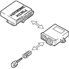
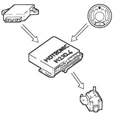
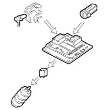
- connection to Alfa Romeo CODE (Immobilizer) control unit
- system self-adaptation
- autodiagnosis
- check on electric cooling fan
The essential conditions that must always be met in the preparation of the air-fuel mixture for the correct operation of controlled-ignition engines are mainly:
- the "metering" (air/fuel ratio) must constantly be kept as close as possible to the stoichiometric ratio, so as to ensure the necessary rapidity of combustion, avoiding unnecessary fuel consumption
- the "homogeneity" of the mixture, consisting of petrol vapours, diffused as finely and evenly as possible in the air.
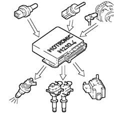
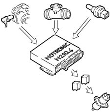
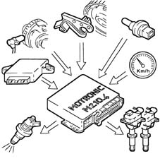
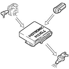
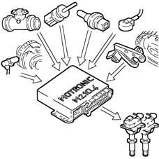
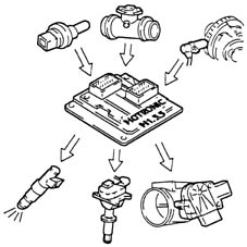
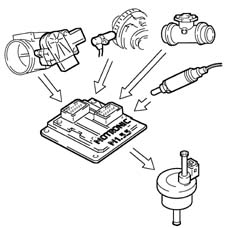
The information processed by the control unit for controlling optimum metering is received in the form of electrical signals emitted by:
- air flow meter and air temperature sensor, for the exact quantity of air drawn in
- rpm sensor, which generates an alternating single-phase signal whose frequency indicates the engine rpm
- throttle position potentiometer (mounted on the throttle body), for recognizing the required acceleration conditions
- coolant temperature sensor located on the thermostat
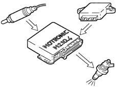
- Lambda sensor for determining the oxygen content in the exhaust gases.
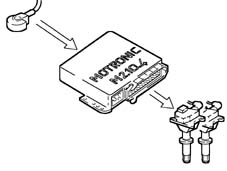
The system has a single coil for each plug (MONOCOIL); the advantages of this solution are:
- less electrical overload;
- guaranteed constant discharge on each plug.
The control unit corrects the advance values mainly in accordance with:
- engine coolant temperature
- intake air temperature
- detonation
- throttle valve position.
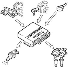
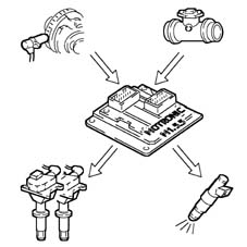
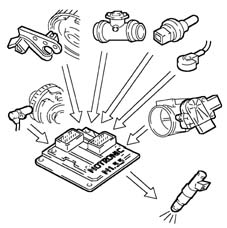
The information the control unit processes in order to drive the single coils is received in the form of electrical signals emitted by the:
- air flow meter and air temperature sensor, for the exact quantity of air drawn in
- rpm sensor, which generates an alternating single-phase signal whose frequency indicates the engine rpm
- knock sensor (on the rear of the engine block between the 2nd and 3rd cylinders) which recognizes which cylinder is knocking and corrects its ignition advance
- throttle valve position potentiometer (mounted on throttle body), which recognizes the minimum load, choke and full load conditions.
Description
General characteristics
The unit comprises the engine and all the systems required for its operation:
- fuel supply system
- air supply system
- engine cooling system
- exhaust system with catalytic converter
- fuel vapour recirculation system.
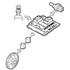
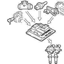
The Bosch Motronic M1.5.5 system belongs to the category of integrated systems:
- inductive discharge digital electronic ignition
- static distribution
- sequential phased electronic fuel injection (1 - 3 - 4 - 2).
During idling, the control unit checks:
- the moment of ignition
- the air flow
System functions are essentially as follows:
- adjustment of fuel injection times
- adjustment of ignition advance values
- check on cold starting
- check on enrichment during acceleration
- fuel cut-off during overrunning
- check and management of idle speed
- limitation of maximum rpm
- check on combustion - Lambda probe
- recognition of cylinder position
- fuel vapour recovery
- connection to air conditioning system (if present)
- connection to Alfa Romeo CODE (Immobilizer) control unit
- system self-adaptation
- autodiagnosis
- check on electric cooling fan
The essential conditions that must always be met in the preparation of the air-fuel mixture for the correct operation of controlled-ignition engines are mainly:
- the "metering" (air/fuel ratio) must constantly be kept as close as possible to the stoichiometric ratio, so as to ensure the necessary rapidity of combustion, avoiding unnecessary fuel consumption
- the "homogeneity" of the mixture, consisting of petrol vapours, diffused as finely and evenly as possible in the air.
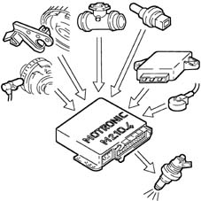
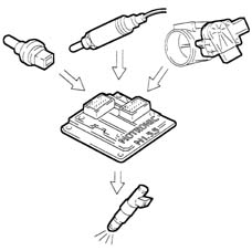
The information processed by the control unit for controlling optimum metering is received in the form of electrical signals emitted by:
- air flow meter and air temperature sensor, for the exact quantity of air drawn in
- rpm sensor, which generates an alternating single-phase signal whose frequency indicates the engine rpm
- throttle valve position potentiometer (built into constant idle speed actuator), which recognizes the idle, choke and full load conditions.
- Lambda sensor for determining the oxygen content in the exhaust gases.
The system has a single coil for each plug (MONOCOIL); the advantages of this solution are:
- less electrical overload;
- guaranteed constant discharge on each plug.
The control unit corrects the advance values mainly in accordance with:
- engine coolant temperature
- intake air temperature
- detonation
- throttle valve position.
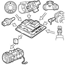
The information the control unit processes in order to drive the single coils is received in the form of electrical signals emitted by the:
- air flow meter and air temperature sensor, for the exact quantity of air drawn in
- rpm sensor, which generates an alternating single-phase signal whose frequency indicates the engine rpm
- knock sensor (on the rear of the engine block between the 2nd and 3rd cylinders) which recognizes which cylinder is knocking and corrects its ignition advance
- throttle valve position potentiometer (built into constant idle speed actuator), which recognizes the idle, choke and full load conditions.
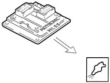
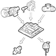
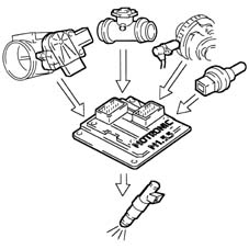
OPERATTION
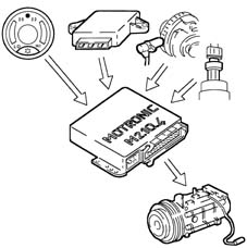
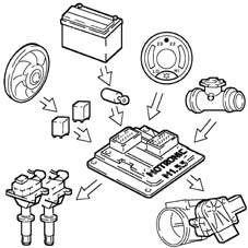
Diagram of input/output information to/from the control unit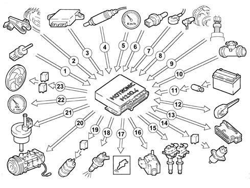
Operating strategy
System self-adaptationThe control unit has a self-adaptation function which recognizes changes in the engine which occur as a result of bedding-in and ageing processes of both components and the engine itself.These changes are stored in the form of modifications to the basic mapping, and their purpose is to adapt the operation of the system to the gradual alterations in the engine and components compared with their characteristics when new.This self-adaptation function also makes it possible to even out inevitable differences (due to production tolerances) in any replaced components.From the exhaust gas analysis, the control unit changes the basic mapping in relation to the original characteristics of the new engine
- warning light on for 4 seconds indicating test stage
- warning light off after 4 secs indicates no faults in components that could affect the values established in emission control regulations
- warning light on after 4 secs indicates fault
- warninglight on indicates fault
- warning light off indicates no faults in components that could affect the values established in emission control regulations
- the control unit, from time to time, defines the type of recovery according to the faulty components
- the recovery parameters are managed by non-faulty components.
The following occurs during cold starting:
- natural weakening of the mixture because of poor turbulence of the fuel particles at low temperatures
- lower evaporation of the fuel
- condensation of the fuel on the inner walls of the inlet manifold
- higher viscosity of the lubricating oil.
The electronic control unit recognizes this condition and corrects the fuel injection times in accordance with:
- coolant temperature
- intake air temperature
- battery voltage
- engine rpm.
The control unit, with the engine in the following conditions:
- idle speed
- medium load
Recovery:
- the control unit replaces the signal coming from the faulty air flow meter with the signal from the throttle valve potentiometer.

During release of the accelerator pedal, and beyond a pre-established threshold, the control unit:
- supply to the fuel injectors cut off
- reactivates the supply to the fuel injectors at 1300-1500 rpm.
The thresholds for reactivation of the fuel supply and for fuel cut-off vary depending on:
- engine coolant temperature
- vehicle speed
- engine rpm.
Depending on the rpm reached by the engine, the control unit:
- over 6800 rpm reduces the injection time
- over 7000 rpm cuts off the supply to the fuel injectors
- under 6800 rpm resumes driving of the fuel injectors.
The control unit supplies the fuel pump:
- when the ignition is ON for 0.8 s
- when the ignition key is on START and the rpm > 225 rpm
The control unit cuts off the supply to the fuel pump:
- ignition in OFF position
- when the engine rpm < 225 rpm.
During a high power demand, the control unit temporarily cuts off the supply to the compressor:
- by switching it off over 6500 rpm
- by switching it off if the engine temperature > 112° C.
During each engine revolution, the control unit recognizes which cylinder is at the power stroke:
- it controls the injection and ignition sequence for the appropriate cylinder.
In the absence of the timing sensor signal, the control unit:
- deactivates the detonation sensor
- with the car moving, maintains phased injection
- with the car stopped, controls simultaneous ignition in cylinders 1-4 and 2-3.
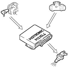
The control unit calculates the injector opening times and controls them extremely quickly and precisely on the basis of:
- engine load (rpm and air flow)
- battery voltage
- engine coolant temperature.
Thanks to the mapping stored in its memory, the control unit can calculate the ignition advance in accordance with:
- engine load (idling, choke, full load depending on the rpm and air flow)
- intake air temperature
- engine coolant temperature
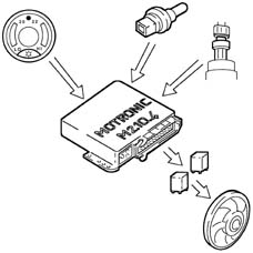
The control unit controls the switching on of the electric fan in accordance with the coolant temperature:
- temperature for switching on 1st speed 93° C
- temperature for switching on 2nd speed 98° C
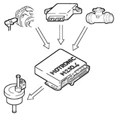
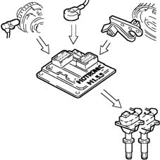
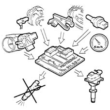
OPERATION
Diagram of input/output information to/from the control unit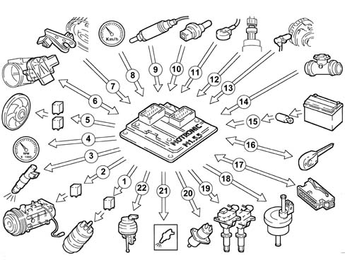
Operating strategy
System self-adaptationThe control unit has a self-adaptation function which recognizes changes in the engine which occur as a result of bedding-in and ageing processes of both components and the engine itself.These changes are stored in the form of modifications to the basic mapping, and their purpose is to adapt the operation of the system to the gradual alterations in the engine and components compared with their characteristics when new.This self-adaptation function also makes it possible to even out inevitable differences (due to production tolerances) in any replaced components.From the exhaust gas analysis, the control unit changes the basic mapping in relation to the original characteristics of the new engineThe self-adaptation parameters are not cancelled if the battery is disconnected.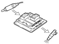
- warning light on for 4 seconds indicating test stage
- warning light off after 4 secs indicates no faults in components that could affect the values established in emission control regulations
- warning light on after 4 secs indicates fault
- warninglight on indicates fault
- warning light off indicates no faults in components that could affect the values established in emission control regulations
- the control unit, from time to time, defines the type of recovery according to the faulty components
- the recovery parameters are managed by non-faulty components.

The following occurs during cold starting:
- natural weakening of the mixture because of poor turbulence of the fuel particles at low temperatures
- lower evaporation of the fuel
- condensation of the fuel on the inner walls of the inlet manifold
- higher viscosity of the lubricating oil.
The electronic control unit recognizes this condition and corrects the fuel injection times in accordance with:
- coolant temperature
- intake air temperature
- battery voltage
- engine rpm.
The control unit, with the engine in the following conditions:
- idle speed
- medium load
- temperature > 30° C
To optimize the quantity of air drawn in by the engine, the control unit checks:
- inlet timing on two angle positions
- geometry of intake ducts on two lengths (only 1.8/2.0 TS).
At the maximum torque speed, the control unit sets the "open" phase:
- cam advanced by 25° engine
- inlet casing long ducts (only 1.8/2.0 TS)
At the maximum power speed, the control unit sets the "closed" phase:
- cam in normal position
- inlet box short ducts (only 1.8/2.0 TS) .
A idle speed, the control unit sets the "closed" phase:
- cam in normal position
- inlet box short ducts.
Recovery:
- the control unit replaces the signal coming from the faulty air flow meter with the signal from the throttle valve potentiometer.
During release of the accelerator pedal, and beyond a pre-established threshold, the control unit:
- supply to the fuel injectors cut off
- reactivates the supply to the fuel injectors at 1300-1500 rpm.
The thresholds for reactivation of the fuel supply and for fuel cut-off vary depending on:
- engine coolant temperature
- vehicle speed
- engine rpm.
Depending on the rpm reached by the engine, the control unit:
- over 6800 rpm reduces the injection time
- over 7000 rpm cuts off the supply to the fuel injectors
- under 6800 rpm resumes driving of the fuel injectors.
The control unit supplies the fuel pump:
- when the ignition is ON for 0.8 s
- ignition in AVV position and engine speed > 23 rpm
The control unit cuts off the supply to the fuel pump:
- ignition in OFF position
- with the engine rpm < 23 rpm.
During a high power demand, the control unit temporarily cuts off the supply to the compressor:
- by switching it off over 6500 rpm
- by switching it off if the engine temperature > 112° C.
During each engine revolution, the control unit recognizes which cylinder is at the power stroke:
- it controls the injection and ignition sequence for the appropriate cylinder.
In the absence of the timing sensor signal, the control unit:
- deactivates the detonation sensor
- with the car moving, maintains phased injection
- with the car stopped, controls simultaneous ignition in cylinders 1-4 and 2-3.
The control unit calculates the injector opening times and controls them extremely quickly and precisely on the basis of:
- engine load (rpm and air flow)
- battery voltage
- engine coolant temperature.
Thanks to the mapping stored in its memory, the control unit can calculate the ignition advance in accordance with:
- engine load (idling, choke, full load depending on the rpm and air flow)
- intake air temperature
- engine coolant temperature
Depending on the devices switched on to control the idle speed (850 ± 30 rpm), the control unit:
- varies the ignition advance
- controls the throttle position (0°-15°) via the idle speed actuator, to regulate the air flow.
The control unit controls the switching on of the electric fan in accordance with the coolant temperature:
- temperature for switching on 1st speed 98° C
- temperature for switching on 2nd speed 101° C