3232883 - 1056F DIRECT PETROL INJECTION SYSTEM
CONSTRUCTION FEATURES
General view
1 - Electric fuel pump
2 - Relays
3 - Lambda sensors upstream of catalytic preconverters
4 - Lambda sensors downstream of catalytic preconverters
5 - Speedometer
6 - Rev counter
7 - Engine Check warning light
8 - Timing sensor
9 - Climate control connector
10 - Diagnostic connector
11 - Alfa Romeo CODE connector
12 - Injection/ignition control unit
13 - Injectors
14 - Coolant temperature sensor
15 - Rpm sensor
16 - Air flow meter with air temperature sensor
17 - Ignition coils
18 - Knock sensor
19 - Fuel vapour recirculation solenoid valve
20 - Accelerator pedal with built-in potentiometer.
21 - Clutch pedal switch
22 - Brake pedal switch
23 - Throttle body integral with D.V.L.
24 - CAN line
25 - Modular intake manifold solenoid valve
26 - Variable valve timing
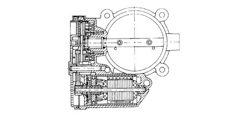
Injection-ignition control unit MED7.1.1
The control unit is fitted in the engine
compartment, on the intake chamber.The control unit memory is the 'flash EPROM'
type, i.e. reprogrammable from the outside without intervening on
the hardware.The adoption of the Alfa Romeo CODE does
not allow control units to be exchanged between vehicles.Replacement of the injection control unit,
air capacity case or the throttle body integral with the D.V.E.
means that the self-learning procedure has to be carried out.PIN-OUT
INJECTORS
These are fitted on the cylinder head and
operated by the injection control unit.They are fastened by means of a fork secured
to the head with a nut.The injector has a single opening with the
fuel sprayed at an angle of 60°.
1 - Fuel intake
2 - O-ring
3 - Electrical connection
4 - Teflon ring
5 - Armature
6 - Coil
PRESSURE PUMP
This is radial jet type with three radial
pistons and is driven by the exhaust camshaft via a spacer.With the engine started, the fuel pressure
in the rail is around 50 bar during idling.During operation, the pressure in the rail
can reach a maximum of 100 bar depending on the engine load conditions.The maximum pressure produced by the pressure
pump is around 120 bar (if the pressure regulator is stuck).The pressure pump must be supplied with
a pressure of at least 4.5 bar; so the fuel system has an auxiliary pump
immersed in the fuel tank.The pressure pump is lubricated and cooled
by the same fuel by means of suitable ducts.
1 - Cylinder
2 - Cam
3 - Piston
4 - Pump shaft
5 - Dynamic seal
6 - Check valve
ENIGINE COOLANT TEMPERATURE SENSOR
This is fitted on the thermostat cup. The
sensitive elements (2 NTC type), contained in a single body, translate
temperature changes into resistance changes to measure coolant temperature.The sensor is produced using semiconductor
technology, so if the temperature of the sensor increases as the temperature
of the coolant increases, the resistance decreases.As the variation in resistance is not linear,
for the same temperature increment, it is higher for low temperatures than
for high temperatures.The following functions are affected
by the sensor:
- coolant temperature information to the engine control
unit
- information for the instrument panel required for readings
displayed to the driver.
The NTC earth connection is insulated from
the sensor case; the sensor therefore comes with a four-way electrical
connection.The engine coolant temperature sensor also
informs the climate control unit.DETONATION SENSOR
The piezoelectric knock sensor is fitted
on the cylinder block/crankcase and detects the intensity of the
vibrations caused by the detonation in the combustion chambers.The piezoelectric crystal forming the sensor
detects the vibrations generated at a frequency of between 12 and 16
kHz, and transforms them into electrical signals sent to the fuel
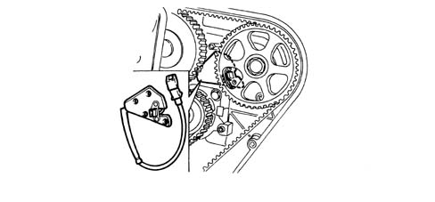
injection control unit.RPM SENSOR
It is fitted on the engine block, where
it faces the phonic wheel located on the crankshaft.The electrical connector of this sensor
is built into the sensor case.Operation
The sensor consists of a tubular casing
(1) which contains a permanent magnet (3) and an electrical winding (2).As the flywheel teeth go past, the magnetic
flow produced by the magnet (3) undergoes fluctuations due to the
change in the gap.These fluctuations induce an electromotive
force in the winding (2), at the ends of which there is a voltage which
alternates between positive (tooth opposite sensor) and negative
(gap opposite sensor).The peak value of the output voltage from
the sensor, provided other factors remain the same, depends on the
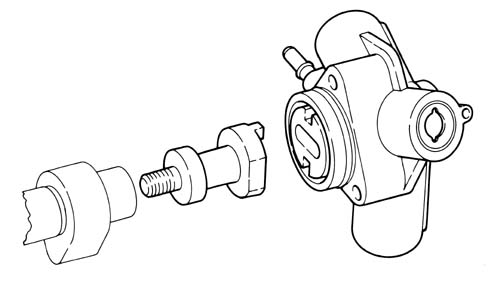
distance between the sensor and tooth (gap).TIMING SENSOR
Hall effect; it is mounted on the cylinder
head and 'facing' the exhaust camshaft pulley.The engine control unit uses the timing
sensor signal for recognizing T.D.C. at the end of compression for
a quick start.ACCELERATOR PEDAL WITH BUILT-IN POTENTIOMETER
The sensor consists of a casing, secured
to the accelerator pedal mount, which contains a shaft, in an axial position,
connected to two potentiometers: one main one and one safety one.The engine control unit implements
the following recovery strategies:
- if there is a fault with one of the two potentiometers,
a throttle opening of up to 25% is allowed for a long period
- if both of the potentiometers fail completely, or one
potentiometer and the brake pedal switch fail, the throttle opening
is excluded.
There is a coil spring on the shaft which
guarantees the correct resistance to the pressure whilst a second spring
ensures the return on release.Operation
The position of the accelerator pedal is
transformed into an electrical voltage signal and is sent to the
fuel injection control unit by the potentiometer connected to the
accelerator pedal.The accelerator pedal position signal is
processed together with the information relating to the rpm, to
obtain the fuel injection times and relevant pressure.THROTTLE BODY WITH DVL
It is fitted on the inlet chamber and regulates
the quantity of air drawn in by the engine.According to the signal coming from the
accelerator pedal potentiometer, the injection control unit controls the
opening of the throttle by means of a direct current motor integrated
in the throttle body integrated with D.V.L.The throttle opening takes place between
0° and 80° therefore including the idle adjustment.The throttle body integral with D.V.L. is
equipped with two potentiometers integrated so that one controls
the other and viceversa.If both the potentiometers fail or
there is no supply, depending on the position of the accelerator
pedal, the control unit reduces the drive torque:
- fully depressed, it cuts off the supply to one or more
pistons, until a maximum speed of 2500 rpm is reached.
- in intermediate positions, it cuts off the supply to
one or more pistons, until a speed below 2500 rpm is reached.
If the throttle body integrated with D.V.L.
or the injection control unit or the air chamber is replaced then
the self-learning procedure must be carried out.Air flow meter
The flow meter is built into the air filter
case and is hot film type.The intake air temperature sensor is built
into the flow meter.
1 - Covers
2 - Electronic card
3 | ... DATA ERROR - CROPPED TEXT | Ошибка данных - Текст обрезан ... |
|---|