3239194 - Introduction - ENGINE
GLOSSARY
GLOSSARY
CONSTRUCTION FEATURES
JTS (uniJet Thrust System) engine with 4 cylinders in line, 1997 cc, static ignition with one plug per cylinder, twin overhead camshaft, electro-hydraulic variable valve timing, hydraulic tappets, 4 valves per cylinder, fuel system with high-pressure pump for direct injection, air supply system with modular inlet manifold, with Bosch Motronic MED7.1.1 integrated injection/ignition.View of engine compartment
.
General characteristics
The unit comprises the engine and all the systems required for its operation:
- fuel system;
- air supply system;
- engine cooling system;
- exhaust system;
- fuel vapour recirculation system
Operation of the fuel injection-ignition
The Bosch Motronic MED7.1.1 system with a motorized throttle belongs to the category of integrated systems with:
- ignition
- sequential and phased electronic injection.
The main operating principles of the system are basically as follows:
- self-learning;
- system self-adaptation;
- autodiagnosis;
- recognition of the Alfa Romeo CODE (Immobilizer);
- control of cold starting;
- control of combustion - Lambda sensors;
- control of variable valve timing and modular inlet manifold
- control of knock;
- control of mixture enrichment during acceleration;
- fuel cut-off with the accelerator pedal released;
- fuel vapour recovery;
- control of the maximum rpm;
- control of high-pressure fuel pump;
- connection to the climate control system
- recognition of cylinder position;
- control of the optimum injection time for each cylinder;
- adjustment of ignition advance values;
- management of the idle speed (also according to the battery voltage);
- control of the electric fans;
- connection with ABS/ASR control unit;
- throttle opening management - CITY (Selespeed version);
- connection with the automatic transmission control unit (where fitted);
- connection with the instrument panel;
- fuel system diagnosis;
- catalyzer diagnosis;
- detection of misfire;
- Lambda sensors diagnosis.
The essential conditions that must always be met in the preparation of the air-fuel mixture for the correct operation of controlled-ignition engines are mainly:
- the 'metering' (air/fuel ratio) should constantly be kept as close as possible to the stoichiometric ratio, so as to ensure the maximum conversion capacity for the catalytic converter (max. efficiency).
- the 'homogeneity' of the mixture, consisting of petrol, diffused as finely and evenly as possible in the air.
The information processed by the control unit for controlling optimum metering is received in the form of electrical signals emitted by:
- air flow meter and air temperature sensor, for the exact quantity of air drawn in;
- rpm sensor which produces an alternating, single-phase signal whose frequency indicates the engine rpm;
- accelerator pedal with throttle potentiometer, to recognize the driver conditions requested;
- – coolant temperature sensor on the thermostat;
The system has a single coil for each plug (MONOCOIL), with integrated power stage; the advantages of this solution are:
- less electrical overload;
- guarantee of constant discharge at each spark plug.
The control unit corrects the advance values mainly in accordance with:
- engine coolant temperature;
- intake air temperature;
- detonation.
The information the control unit processes in order to drive the single coils is received in the form of electrical signals emitted by:
- air flow meter and air temperature sensor, for the exact quantity of air drawn in;
- rpm sensor which produces an alternating, single-phase signal whose frequency indicates the engine rpm;
- detonation sensors to recognize the cylinder where detonation is occurring and correct the ignition advance;
- throttle potentiometer, to recognize the minimum, partial and full load conditions;
- timing sensor.
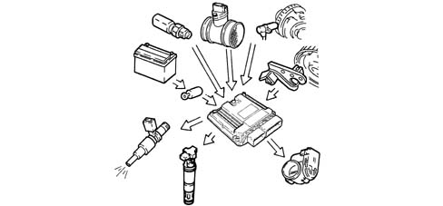
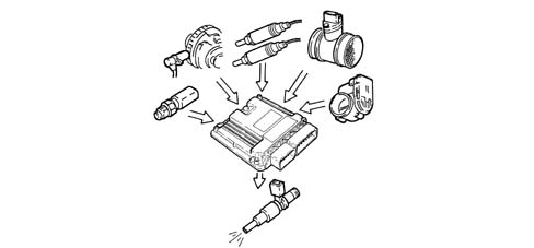
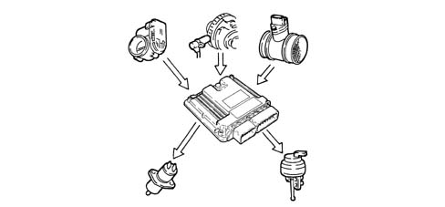
OPERATING
Diagram of input/output info to/from control unit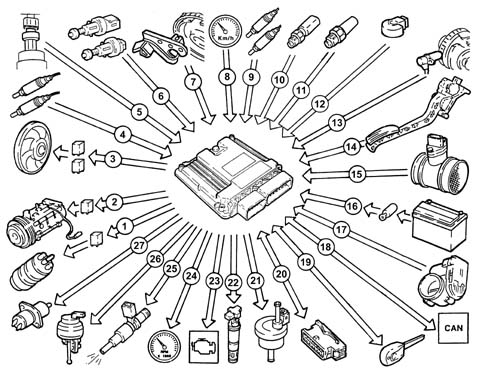
System operating modes
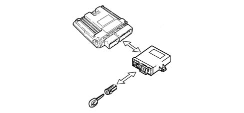
Self-learningThe control unit implements the self-learning mode in the following conditions:
- installation of new injection control unit,
- installation of a new throttle body actuator integratd with D.V.L.
- installation of a new modular intake manifold.
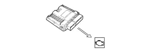
The (MIL) warning light operating logic is as follows:
- with the ignition key in the ON position, the warning light comes on and remains on until the engine has been started up. The control unit's self-test checks the signals coming from the sensors, comparing them with the permitted limits:
Signalling of faults during engine starting:
- the failure of the warning light to go out after the engine has been started up means that there is an error memorized in the control unit.
Fault indication during operation
- the warning light flashing indicates possible damage to the catalytic converter due to misfire.
- the warning light on constantly indicates the presence of engine management errors or EOBD errors.
In cold starting conditions there is a natural weakening of the mixture which causes poor evaporation of the fuel at low temperatures:
- condensation of the fuel on the inner walls of the inlet manifold;
- increased viscosity of the lubricant oil.
The electronic control unit recognizes this condition and corrects the fuel injection time in accordance with:
- coolant temperature;
- intake air temperature;
- battery voltage;
- engine rpm.
To optimize the quantity of air drawn in by the engine, the control unit checks:
- inlet timing at two angular positions;
- geometry of inlet ducts over two lengths.
At the maximum torque speed, the control unit sets the open phase:
- cam advanced by 25° engine;
- modular inlet manifold long ducts
At the maximum power speed, the control unit sets the closed phase:
- cam in normal position
- modular inlet manifold short ducts.
At idle speed, the control unit sets the closed phase:
- cam in normal position
- modular inlet manifold short ducts.
The control unit can delay the ignition selectively at the cylinder required, according to the combination of figures received from the detonation and timing sensors and:
- reduces the ignition advance in steps of 3° up to a maximum of 9°;
- updates the level to take into account background noise and ageing of the engine
With the auto-adjustment function, the control unit
| ... DATA ERROR - CROPPED TEXT | Ошибка данных - Текст обрезан ... |
|---|