3239209 - Introduction - MANUAL GEARBOX AND DIFFERENTIAL
DESCRIPTION
Gearbox structure
The structure of the gearbox consists of:
- gearbox casing which contains and supports the main and layshafts, rods and gear selector forks and the gear selector and engagement device.
- a rear cover which contains the 5th speed gears, the 5th speed engagement fork and the rear bearing retaining plate for the main and layshafts
- the bell housing which contains the clutch and the coaxial clutch control

Main shaft
The main shaft consists of:
- 1st , Reverse and 2nd speed gears
- 3rd , 4th , 5th speed gears, fitted on needle bearings with the synchronizers
3 rd , 4 th and 5 th speed gears fitted on the shaft make it possible to:
- reduce shift loads during synchronisation
- reduce gearbox noise while in neutral.
Layshaft
The layshaft consists of:
- 1st and 2nd speed gears, fitted on needle bearings with synchronizers
- 3rd , 4th and 5th speed gears fitted on the shaft.
The layshaft is supported on:
- a roller bearing at the pinion end
- a ball bearing at the cover end.
Gears
The gears are the following type:
- helical toothed for the forward speeds
- straight toothed for Reverse.
Synchronizers
The synchronizers for all the gears are brass, baulk ring, single-cone "Borg-Warner" type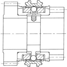
Gear shift/selection system
The gear shift/selection system consists of:
- a swinging control (1) connected to selector dog (2)
- selector dog (2) which operates sliding rods (4) fitted with synchronisation sleeve control forks (3, 5, 6, 7).

Safety devices
The safety devices consist of:
- three dowels (1) that prevent two speeds being engaged at the same time
- dowel (3), pin (4) and spring (5), which maintain reversing dog (2) in a safe position to prevent dangerous movements of revesing fork (9) with the attendant possibility of engaging reverse.
- Lever (10) and spring (11), which prevent involuntary engagement of revese while changing from 5th to 4th speed.

Differential
The differential consists of:
- a crown wheel and pinion reduction
- a differential housing constructed in a single piece which includes the differential and planet gears.