3239074 - 1024A10 crank shaft - r + r with engine removed - check main and connecting rod bearingand replace if necessary

Removing
(
Refitting
)
Proceed with removal
- 1004D40 engine - position on stand
and remove
.
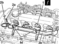
1. Disconnect the electrical connections from the ignition coils.
| Name | Connector |
|---|
| 1 | Ignition coil | A30 |
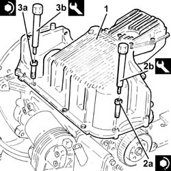
2. Undo nut (2a) and disconnect earth lead (2b) from the cam cover.3. Undo the bolts (3a) and move wiring duct (3b) aside.
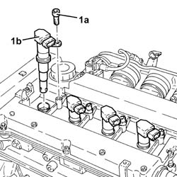
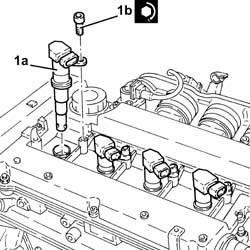
1. Undo the bolts (1a) and remove the ignition coil (1b).
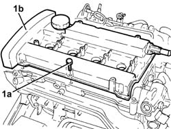
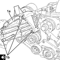
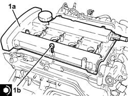
1. Undo the bolts (1a) and remove the tappet cover (1b), complete
with seal.
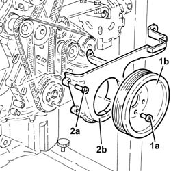
1. Undo the bolts (1a) and remove the crankshaft pulley (1b).2. Undo the bolts (2a) and rmeove the lower timing cover (2b).
1. Loosen the nut for the counter-balance shaft toothed drive belt
tensioner.2. Release and remove the counter-balance shaft drive belt.
1. Loosen the nut securing the timing belt mobile tensioner.2. Prise off and remove the timing belt.
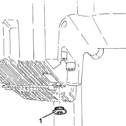
1. Undo the plug and drain the engine oil. | Collect the engine oil in a suitable
container. |
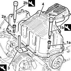
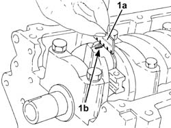
Rotate the engine through 180° on the
overhauling stand.1. Undo the front and rear bolts (1a) securing the crankcase sump
using tool (1b).
| Name | Country |
|---|
| 1b | Spanner | 1.860.833.001 |
2. Undo the side bolts (2a) securing the crankcase sump using tool
(2b).
| Name | Country |
|---|
| 2b | Spanner | 1.860.834.001 |
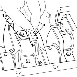
3. Use the tool to cut the crankcase sump sealant.
| Name | Country |
|---|
| 3 | Blade | 1.870.718.000 |
4. Remove the crankcase sump.
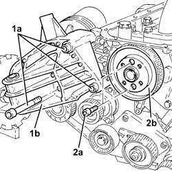
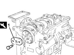
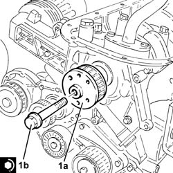
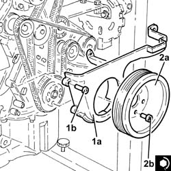
1. Undo the nuts (1a) and remove the timing side rigid engine support
(1b).2. Undo the bolts (2a) and remove the counter-rotating balancer
shaft drive belt drive pulley (2b).
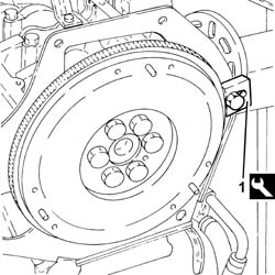
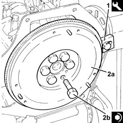
1. Fit the flywheel lock.
| Name | Country |
|---|
| 1 | Counter-torque | 1.860.846.001 |
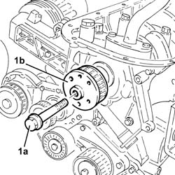
1. Undo the bolt (left) (1a) and remove the drive pulley (1b).
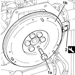
1. Undo the bolts (1a) and remove the engine flywheel (1b). | The engine flywheel retaining
bolts are treated with a compound to prevent them coming undone
they should therefore be replaced whenever they are removed. |
2. Remove the flywheel lock.
| Name | Country |
|---|
| 2 | Counter-torque | 1.860.846.001 |
1. Undo the bolts (1a) and remove the engine flywheel protection
(1b).
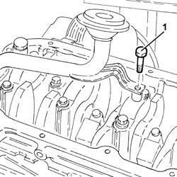
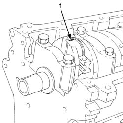
1. Undo the bolt securing the engine oil intake to the main bearing
cap.
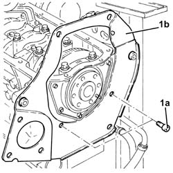
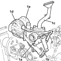
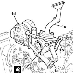
1. Undo bolts (1a) and remove the crankshaft front cover (1b) with
built-in oil pump complete with inlet (1c), engine oil heat exchanger
(1d) and engine oil filter (1e). 2. Remove the gasket.
Prise out the oil seal from the front crankcase
cover. | Take care not to damage the oil
seal seat during removal. |
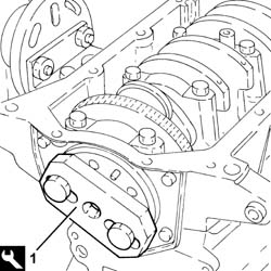
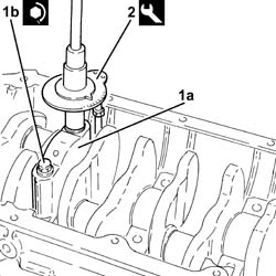
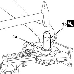
1. Fit the tool for rotating the crankshaft.
| Name | Country |
|---|
| 1 | Flange | 1.820.618.000 |
Turn the crankshaft using the tool fitted
previously to gain access to the big end bearing cap bolts.1. Undo the bolts (1a) and remove the connecting rod caps (1b) and
bearing shells (1c).2. Remove the tool for rotating the crankshaft.
| Name | Country |
|---|
| 2 | Flange | 1.820.618.000 |
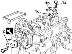
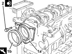
1. Undo the bolts (1a) and remove the crankcase rear cover with
the oil seal integrated (1b).
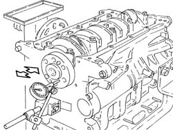
Check that the crankshaft end float is
within the recommended values using a magnetic base fitted with
a dial gauge.
| Measurement | | Value |
|---|
| - | Crankshaft end float (mm) | | 0.059 ÷ 0.221 |
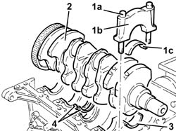
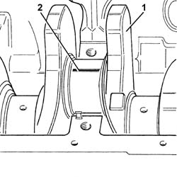
1. Undo the bolts (1a) and remove the main bearing caps (1b) complete
with bearing shells (1c).2. Remove the crankshaft.3. Remove the half-bearings.4. Remove the thrust washers.
Refitting
(
Removing
)
Check that the main bearing halves are
not scored and that they do not show traces of binding. if this
is not the case, replace them. | The bearing halves must not be
adapted in any way. |
Check that the thickness of the main journal
half-bearings is within the recommended values; if this is not the
case, replace them. if this is not the case, replace them.
| Measurement | | Value |
|---|
| - | Crankshaft bearing thickness (mm) | Category B | 1.839 ÷ 1.843 |
| Category C | 1.842 ÷ 1.846 |
| Class A | 1.836 ÷ 1.840 |
Check that the thickness of the connecting
rod half-bearings is within the recommended values; if this is not
the case, replace them. if this is not the case, replace them.
| Measurement | | Value |
|---|
| - | Crankpin thickness (mm) | Category B | 1.530 ÷ 1.534 |
| Category C | 1.533 ÷ 1.537 |
| Classe A | 1.527 ÷ 1.531 |
| Specially-selected main and crankshaft
half-bearings are fitted to this engine to ensure that the matching
clearance is optimum. |
| The crankshaft is supplied, by
the Parts Dept., without the appropriate half-bearings for 'standard'
dimension main journals and crank pins; it is therefore necessary
to select the half-bearings to be fitted by identifying the grade
for each main journal and crank pin for the new crankshaft. |
The following is needed for selecting
the main journal half-bearings:
- the code number stamped on the phonic wheel;
- the paint mark, if present, next to the main journals.
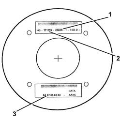
Below is an example of the identification
of main journal grades.
1 - Crank pin identification number: the
number on the left refers to the first timing side bearing; the
final 'N' is a code that does not matter for 4 cylinder engines.
2 - Main journal identification code: the
first number on the left refers to the first timing side bearing;
the final 'N' is a code that does not matter for 4 cylinder engines.
3 - Set of numbers (if present), in groups
of two digits, which indicate the dimensions (thousandth part) of
the crankpins: the first two numbers on the left refer to the first
pin on the timing side. | Only use the codes in the key,
all other codes on the flywheel should not be used. |
For the identification of the main journal
grade, refer to the numerical code for reference 2 in the key.In the case of the example, the numbers
11111N indicate that all five bearings are Grade A (red colour)
as described below.A further method for identifying the grade
of the bearings is to read reference 3 in the figure (if present).In the case of the example, the number
84 (first on the left) corresponds to the dimension 52.984 for the
first bearing on the timing side which identifies Grade A (red colour);
the same method can be used for all 87 - 85 - 85 - 8497 - 95 -
95 - 94). MAIN JOURNAL IDENTIFICATIONGrade A main journal (standard), diameter
52.982 52.988 mm, RED paint mark, code number 1 (82 88)* Grade B main journal (normal), diameter
52.988 52.994 mm, BLUE paint mark, code number 2 (88 94)*Grade C main journal (standard), diameter
52.984 53.000 mm, YELLOW paint mark, code number 3 (94 00)* Grade D main journal (0.127 undersize)
diameter 52.855 52.861 mm, BROWN paint mark, code number 6 (55
61)* Grade E main journal (0.127 mm undersize)
diameter 52.861 52.867 mm, GREEN paint mark, code 7 (61 67)* Grade F main journal (0.127mm undersize)
diameter 52.867 52.873 mm, BLACK paint mark, code number 8 (67
73)* (*) Last two numbers (thousandth part)
of the dimensions of the main journals. If a crankshaft is being used where the
maximum bearing undersize through regrinding is 0.127 mm, then the
grade should be selected by measuring the dimensions of the diameter
of the bearing with reference to the above. Having defined the grade and colour for
each new or reground crankshaft bearing, it is necessary to select the
pair and the size for the bearings which should be the same colour
as the corresponding bearing; at the Parts Dept. it is possible
obtain the part no. of the pair of half-bearings required The above is designed to ensure the optimum
operating clearance for all bearings.Lastly, we wish to point out that, usually,
the clearance between the main journal and the half-bearing, produced
by the selection method described above, should be 0.031 0.051 mm;
this value can be measured, as a final check, using the Plastic
Gauge as described below. Place the main half-bearings, selected
as described above, back in their housings in the cylinder block/crankcase. | Observe scrupulous cleanliness
during assembly. |
1. Place the crankshaft back in its housing.2. Fit the calibrated wire (Plastigage) to measure the main journal
clearance.
1. Place the bearing cap (1a), complete with half-bearing, back
in its housing and secure it by tightening the nuts (1b) to the
recommended torque. | The bearing caps are marked with
progressive reference notches (from zero to four starting from the
front of the engine) which define their fitting position. |
| The safety notches on the crankcase
and main bearing caps must all be on the same side. |

| Fastening | Component | Ø | Value(daNm) |
|---|
| 1b | Nut | MAIN BEARING CAPS | M12 | (Engine crankcase side) 2.5 + 79° |
2. Use the tool for angular tightening of the main bearing cap bolts.
| Name | Country |
|---|
| 2 | Protractor | 1.860.942.000 |
1. Remove the bearing caps fitted previously and, using a suitable
graduated measuring instrument (1a), measure the clearance shown
by the calibrated wire (1b). | Measure the clearance at all the
bearings, taking care to carry out this operation, one bearing at
a time, without ever moving the crankshaft. |
| Measurement | | Value |
|---|
| 1 | Crankpin/bearing shell play (mm) | | 0.031 ÷ 0.051 |
| If the readings are not within
the specified range, replace the main bearing halves with new bearing
halves of appropriate size and category. |
Refit the main bearing halves.Place the thrust washers (thickness depending
on the crankshaft endfloat measured during the dismantling) back
in their housings in the third main bearing. | The lubrication ducts in the thrust
washers are fitted facing the crankshaft shoulder. |
Place the crankshaft back in its housing.1. Place the bearing caps (1a), complete with half-bearings, back
in their housings and secure them by tightening the nuts (1b) to
the recommended torque. | The bearing caps are marked with
progressive reference notches (from zero to four starting from the
front of the engine) which define their fitting position. |
| The safety notches on the crankcase
and main bearing caps must all be on the same side. |
| Fastening | Component | Ø | Value(daNm) |
|---|
| 1b | Bolt | MAIN BEARING CAPS | M12 | 2.4 ÷ 2.6 + 100? |
2. Use the tool for angular tightening of the main bearing cap bolts.
| Name | Country |
|---|
| 2 | Protractor | 1.860.942.000 |
1. Fit the tool for rotating the crankshaft.
| Name | Country |
|---|
| 1 | Flange | 1.820.618.000 |
| Specially-selected main and crankshaft
half-bearings are fitted to this engine to ensure that the matching
clearance is optimum. |
| The crankshaft is supplied, by
the Parts Dept., without the appropriate half-bearings for 'standard'
dimension main journals and crank pins; it is therefore necessary
to select the half-bearings to be fitted by identifying the grade
for each main journal and crank pin for the new crankshaft. |
The following is needed for selecting
the main journal half-bearings
- the code number stamped on the phonic wheel;
- the paint mark, if present, next to the crankpins.
Below is an example of the identification
of crankpin grades.
1 - Crank pin identification number: the
number on the left refers to the first timing side bearing; the
final 'N' is a code that does not matter for 4 cylinder engines.
2 - Main journal identification code: the
first number on the left refers to the first timing side bearing;
the final 'N' is a code that does not matter for 4 cylinder engines.
3 - Set of numbers (if present), in groups
of two digits, which indicate the dimensions (thousandth part) of
the crankpins: the first two numbers on the left refer to the first
pin on the timing side. | Only use the codes in the key,
all other codes on the flywheel should not be used. |
For the identification of the crankpin
grade, refer to the numerical code for reference 1 in the key. In the case of the example, the numbers
2222N indicate that all four bearings are Grade B (blue) as described
belowCRANKPIN IDENTIFICATIONCrankpin grade A (standard), diameter 50.787
50.793 mm, RED paint spot, code number 1 (87 93)* Grade B crankpin (standard), diameter
50.793 50.799 mm, BLUE paint mark, code number 2 (93 99)* Grade C crankpin (standard), diameter 50.799
50.805 mm, YELLOW paint mark, code number 3 (99 05)* Grade D crankpin (0.127mm undersize) diameter 50.660
50.666 mm, BROWN paint mark, code number 6 (60 66)*Grade E crankpin (0.127 mm undersize) diameter 50.666
50.672 mmmm, GREEN paint mark, code 7 (66 72)*Grade F crankpin (0.127 undersize) diameter
50.672 50.678 mm, BLACK paint mark, code number 8 (72 78)* (*) Last two numbers (thousandth part)
of the dimensions of the main journals. If a crankshaft is being used where the
maximum bearing undersize through regrinding is 0.127 mm, then the
grade should be selected by measuring the dimensions of the diameter
of the bearing with reference to the above. Having defined the grade and colour for
each new or reground crankshaft bearing, it is necessary to select the
pair and the size for the bearings which should be the same colour
as the corresponding bearing; at the Parts Dept. it is possible
obtain the part no. of the pair of half-bearings required The above is designed to ensure the optimum
operating clearance for all bearings.Lastly, we wish to point out that, usually,
the clearance between the crankpin and the half-bearing, produced by
the selection method described above, should be 0.030 0.056 mm.
this value can be measured, as a final check, using the Plastic
Gauge as described below. Turn the crankshaft to gain access to the
crankpins.1. Fit the calibrated wire (Plastigage) to measure the relevant
crankpin clearances.
1. Refit the connecting rod cap (1a) complete with half-bearin,
selected as described previously, and secure by tightening the bolts
(1b) to the recommended torque. | The safety notches on the connecting
rod cap and connecting rod head must be on the same side. |
| Fastening | Component | Ø | Value(daNm) |
|---|
| 1b | Bolt | BIG END BEARING CAPS | M9 | 2.4 ÷ 2.6 +60? |
2. Use the tool for angular tightening of the connecting rod cap
bolts.
| Name | Country |
|---|
| 2 | Protractor | 1.860.942.000 |
1. Remove the connecting rod cap fitted previously and, using a
suitable graduated measuring instrument (1a), measure the clearance
shown by the calibrated wire (1b). | Measure the clearance at all the
bearings, taking care to do it one bearing at a time without ever moving
the crankshaft. |
| Measurement | | Value |
|---|
| - | Crankpin/big end bearing play (mm) | | 0.030 ÷ 0.056 |
| If the value measured does not
correspond to the recommended figures, replace the connecting rod
half bearings with new ones of appropriate size and category. |
1. Refit the connecting rod bearing caps (1a), complete with half-bearings
and secure them by tightening bolts (1b) to the recommended torque. | The safety notches on the connecting
rod cap and connecting rod head must be on the same side. |
| Fastening | Component | Ø | Value(daNm) |
|---|
| 1b | Bolt | BIG END BEARING CAPS | M9 | 2.4 ÷ 2.6 +60? |
2. Use the tool for angular tightening of the connecting rod cap
bolts.
| Name | Country |
|---|
| 2 | Protractor | 1.860.942.000 |
Remove the tool for rotating the crankshaft.
| Name | Country |
|---|
| - | Flange | 1.820.618.000 |
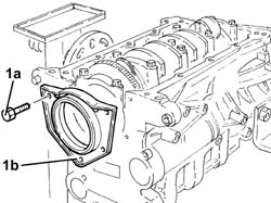
1. Refit the rear crankcase cover with built-in oil seal (1a) using
tool (1b).
| Name | Country |
|---|
| 1b | Fitting tool | 1.820.619.000 |
2. Tighten the rear crankcase cover bolts with the built-in oil
seal to the specified torque.
| Fastening | Component | Ø | Value(daNm) |
|---|
| 2 | Bolt | CRANKSHAFT REAR COVER | M6 | (Engine crankcase side) 0.8 ÷ 1.0 |
1. Refit oil seal (1a) in the front crankcase cover using tool (1b).
| Name | Country |
|---|
| 1b | Fitting tool | 1.821.147.000 |
Rotate the engine throughi 180° on the
overhauling stand.1. Fit the engine block front cover (1a) with built-in oil pump
complete with gasket (1b), intake chamber (1c) and engine oil heat
exchanger (1d). 2. Tighten the crankcase front cover bolts to the specified torque.
| Fastening | Component | Ø | Value(daNm) |
|---|
| 2 | Bolt | CRANKSHAFT FRONT COVER | M6 | (Engine crankcase side) 0.8 ÷ 1.0 |
Tighten the engine oil air intake bolt
to the main bearing cap.Place the engine flywheel protection back
in its housing and secure it using the bolts.1. Fit the flywheel lock.
| Name | Country |
|---|
| 1 | Counter-torque | 1.860.846.000 |
2. Refit the engine flywheel (2a) and secure by tightening new sealant-treated
bolts (2b) to the recommended torque. | The engine flywheel retaining
bolts are treated with a compound to prevent them coming undone
they should therefore be replaced whenever they are removed. |
| Fastening | Component | Ø | Value(daNm) |
|---|
| 2b | Bolt | FLYWHEEL | M12 | (Crankshaft side) 14.4 ÷ 17.6 |
Use the tool for angular tightening of
the engine flywheelbolts.
| Name | Country |
|---|
| - | Protractor | 1.860.942.000 |
1. Place the toothed drive pulley (1a) back in its housing and secure
it by tightening the bolt (left hand thread) (1b) to the recommended
torque.
| Fastening | Component | Ø | Value(daNm) |
|---|
| 1b | Bolt with left hand thread | TOOTHED DRIVE PULLEY | M16 | (Crankshaft side) 20.9 ÷ 23.1 |
Remove the flywheel lock.
| Name | Country |
|---|
| - | Counter-torque | 1.860.846.001 |
1. Refit the timing side rigid engine support (1a)and secure it
tightening the bolts (1b) to the recommended torque.
| Fastening | Component | Ø | Value(daNm) |
|---|
| 1b | Bolt | ENGINE MOUNT TIMING SIDE | M10 | (Crankcase side) 4.5 ÷ 5.5 |
Apply silicon sealant around the edge of
the crankcase sump.1. Position the sump on the crankcase.2. Tighten the front and rear bolts (2a) fixing the crankcase sump
to the recommended torque using the tool (2b).
| Fastening | Component | Ø | Value(daNm) |
|---|
| 2a | Front and rear bolts | OIL SUMP | M6 | (Engine crankcase side) 0.8 ÷ 1.0 |
| Name | Country |
|---|
| 2b | Spanner | 1.860.833.001 |
3. Tighten the side bolts (3a) fixing the crankcase sump to the
recommended torque using the tool (3b).
| Fastening | Component | Ø | Value(daNm) |
|---|
| 3a | Side bolts | OIL SUMP | M8 | (Engine crankcase side) 2.3 ÷ 2.8 |
| Name | Country |
|---|
| 3b | Spanner | 1.860.834.001 |
Tighten the engine oil drain plug to the
specified torque.
| Fastening | Component | Ø | Value(daNm) |
|---|
| - | - | ENGINE OIL DRAIN PLUG | M18 | (Crankcase sump side) 1.8 ÷ 2.2 |
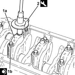
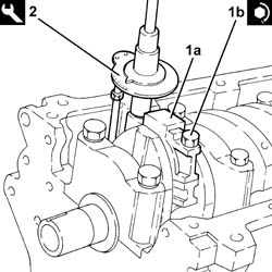
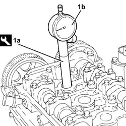
Rotate the engine throughi 180° on the
overhauling stand.1. Fit the tool (1a), complete with dial gauge (1b), in the housing
of the spark plug for cylinder no. 1.
| Name | Country |
|---|
| 1a | Extension | 1.860.895.001 |
Rotate the crankshaft in a clockwise direction
until the piston for cylinder no. 1 is at T.D.C. in the explosion stroke. | If T.D.C. is exceeded, do not
turn backwards, but proceed by rotating the crankshaft through a further
two revolutions in the same direction until the piston for cylinder
no. 1 is at T.D.C. |
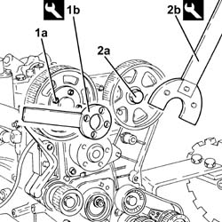
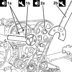
1. Undo the bolts (1a) of the timing driven pulley, inlet side,
using the tool (1b) for counter-torque.
| Name | Country |
|---|
| 1b | Counter-torque | 1.860.856.001 |
2. Loosen the bolt (2a) for the exhaust -side driven toothed pulley,
using tool (2b) for counter-torque.
| Name | Country |
|---|
| 2b | Spanner for camshaft pulley rotation | 1.860.831.002 |
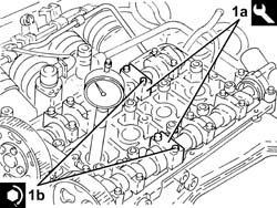
Undo the bolts and remove the 4th cap on
the inlet side camshaft and the 2nd cap on the exhaust side camshaft.1. Fit the tool (1a) in place of the camshaft caps removed and fix
it tightening the bolts (1b) to the recommended torque. | Check that the camshaft cam profile
matches the tool correctly. |
| Name | Country |
|---|
| 1a | Gauge | 1.870.859.000 |
| Fastening | Component | Ø | Value(daNm) |
|---|
| 1b | Bolt | ENGINE TIMING ADJUSTMENT TEMPLATES | M7 | (Cylinder head side) 1.0 |
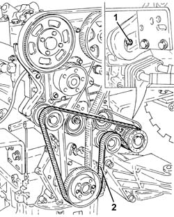
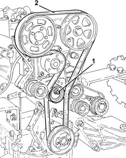
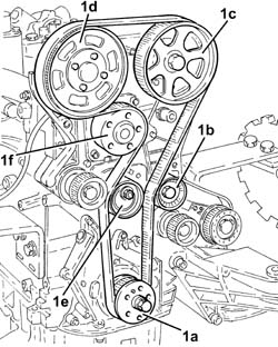
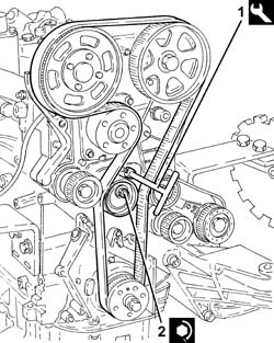
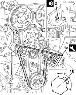
1. Fit the timing belt, following the order indicated in the diagram.toothed drive pulley (1a)fixed tensioner (1b)exhaust side toothed driven pulley (1c) | Before fitting the belt on the
exhaust side driven pulley, rotate it in a clockwise direction (see diagram)
until the end of travel position. |
inlet side toothed driven pulley (1d). | Before fitting the belt on the
inlet side driven pulley, rotate it in a clockwise direction (see diagram)
until the end of travel position. |
mobile tensioner (1e)coolant pump pulley (1f). | When fitting, ensure that the
arrow stamped on the belt is facing in the direction of engine rotation
(clockwise - timing side). |
1. Using the tool, rotate the timing moving tensioner until the
maximum tension is applied to the timing belt.
| Name | Country |
|---|
| 1 | Key | 1.822.149.000 |
2. Tighten the nut for the moving tensioner to the recommended torque.
| Fastening | Component | Ø | Value(daNm) |
|---|
| 2 | Nut | MOBILE TIMING TENSIONER | M8 | 2.3 ÷ 2.8 |
1. Tighten the bolts (1a) for the camshaft driven pulley, inlet
side, to the recommended torque using the tool (1b) for counter-torque.
| Fastening | Component | Ø | Value(daNm) |
|---|
| 1a | Bolt | TIMING GEAR DRIVEN PULLEYS | M6 | (Inlet camshaft side) 0.8 ÷ 1.0 |
| Name | Country |
|---|
| 1b | Counter-torque | 1.860.856.001 |
2. Tighten the bolt (2a) securing the exhaust side timing driven
pulley to the recommended torque, using the tool (2b) for counter-torque.
| Fastening | Component | Ø | Value(daNm) |
|---|
| 2a | Bolt | TIMING GEAR DRIVEN PULLEYS | M12 | (Exhaust camshaft side) 10.8÷13.2 |
| Name | Country |
|---|
| 2b | Spanner for camshaft pulley rotation | 1.860.831.002 |
Remove the tool for timing the camshafts.
| Name | Country |
|---|
| - | Gauge | 1.870.859.000 |
Place the previously removed camshaft caps
back in their housings and secure them tightening the bolts to the
recommended torque.
| Fastening | Component | Ø | Value(daNm) |
|---|
| - | Bolt | CAMSHAFT SUPPORTS | M7 | (Cylinder head side) 1.4 ÷ 1.7 |
Rotate the crankshaft through two revolutions
in its direction of rotation (clockwise - timing side) and ensure
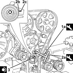
that the piston for cylinder no. 1 is at TDC.1. Fit the tool (1a) for keeping the moving timing tensioner still
and loosen the tensioner nut (1b).
| Name | Country |
|---|
| 1a | Key | 1.822.149.000 |
2. Rotate the tool (2a) in an anti-clockwise direction (timing side)
until the tensioner moving reference (2b) coincides with the reference
opening (2c).
| Name | Country |
|---|
| 2a | Key | 1.822.149.000 |
3. Tighten the nut for the moving tensioner to the recommended torque.
| Fastening | Component | Ø | Value(daNm) |
|---|
| 3 | Nut | MOBILE TIMING TENSIONER | M8 | 2.3 ÷ 2.8 |
Rotate the crankshaft through two revolutions
in its direction of rotation (clockwise - timing side) until cyllinder
no. 1 is at TDC in the explosion stroke and check that the engine
timing is correct using the tool.
| Name | Country |
|---|
| - | Gauge | 1.870.859.000 |
Remove the tool to check T.D.C. from the
cylinder 1 spark plug socket.
| Name | Country |
|---|
| - | Extension | 1.860.895.001 |
Place the spark plug for cylinder no. 1
back in its housing and tighten them to the recommended torque.
| Fastening | Component | Ø | Value(daNm) |
|---|
| - | - | SPARK PLUGS | M14 | (Cylinder head side) 2.4 ÷ 3.0 |
Place the counter-balance shaft drive belt
drive pulley back in its housing and secure it tightening the bolts
to the recommended torque.
| Fastening | Component | Ø | Value(daNm) |
|---|
| - | Bolt | COUNTER-ROTATING SHAFT DRIVE PULLEY | M6 | (Timing drive pulley side.) 0.8÷1.0 |
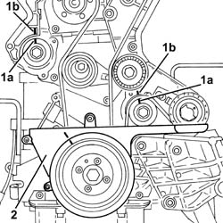
1. Rotate the counter-balance shafts so that the references (1a)
on the pullies are aligned with the ribs (1b).2. Temporarily fit the lower timing cover and the crankshaft pulley
and check the alignment of the references. Fit the counter-balance shaft toothed drive
belt.
1. Tension the counter-balance shaft drive belt using the tool (1a)
so that the reference opening (1b) in the belt tensioner is at the
centre of the rotation sector.
| Name | Country |
|---|
| 1a | Key | 1.822.154.000 |
2. Tighten the nut fixing the counter-balance shaft drive belt
tensioner to the recommended torque.
| Fastening | Component | Ø | Value(daNm) |
|---|
| 2 | Nut | COUNTER-ROTATING SHAFT BELT TENSIONER | M6 | (.Left. counter balance shaft front) cover
side 0.8÷1.0 |
1. Fit the lower protective timing cover (1a) and secure using the
bolts (1b).2. Place the crankshaft pulley (2a) back in its housing and secure
it by tightening bolts (2b) to the recommended torque.
| Fastening | Component | Ø | Value(daNm) |
|---|
| 2b | Bolt | CRANKSHAFT PULLEY | M8 | 2.3 ÷ 2.8 |
1. Place the tappet cover (1a), complete with gasket, back in its
housing and secure it tightening the bolts (1b) to the recommended
torque.
| Fastening | Component | Ø | Value(daNm) |
|---|
| 1b | Bolt | CAM COVER | M6 | (Cylinder head side) 0.8 ÷ 1.0 |
1. Place the ignition coils (1a) back in their housings and secure
them by tightening bolts (1b) to the recommended torque.
| Fastening | Component | Ø | Value(daNm) |
|---|
| 1b | Bolt | IGNITION COIL/REEL | M6 | (Tappet cover side) 0.8 ÷ 1.0 |
Refit the wiring duct and secure with bolts.Connect the earth lead to the tappet cover
and secure it with its bolt.Connect the electrical connections to the
ignition coils.
Proceed with refitting
- 1004D40 engine - position on stand
and remove
.