3239194 - Introduction - ENGINE
GLOSSARY
GLOSSARY
CONSTRUCTION FEATURES
6 cylinder engine in a 60° V formation,
3179 c.c., static advance ignition with a twin overhead camshaft
for each cylinder head, hydraulic tappets, 4 valves per cylinder,
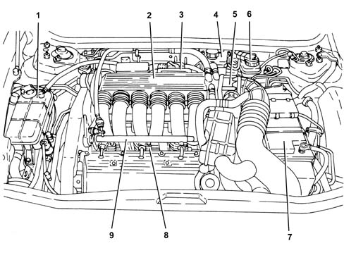
Bosch Motronic ME2.1 integrated injection/ignition system.View of engine compartment
.
1 - Engine coolant reservoir
2 - Air chamber
3 - Injection - ignition control unit
4 - Power steering fluid reservoir
5 - Throttle body integrated with D.V.L.
6 - Brake - clutch fluid reservoir
7 - Battery
8 - Fuel injectors
9 - Fuel manifold pipe
General characteristics
The unit comprises the engine and
all the systems required for its operation:
- fuel system;
- air supply system;
- engine cooling system;
- exhaust system;
- fuel vapour recirculation system.
The operation of these systems is optimized
by an electronic control system governed by a control unit.An understanding of the operating logic
of the control unit gives an overall picture of the entire GROUP
10 system.Operation of the injection/ignition system
The Bosch Motronic ME7.3.1 system
with a motorized butterfly belongs to the category of integrated
systems with:
- ignition
- sequential and phased electronic injection.
The control unit controls the air flow rate
at the idle rotation speed set by the electronic throttle.The control unit controls the moment of
ignition with the advantage of keeping the engine running smoothly as
the ambient parameters and loads applied vary.The control unit controls and manages fuel
injection so that the stoichiometric ratio (air/fuel) is always
at the optimum value.The main operating principles of
the system are basically as follows:
- self-learning;
- sytem self-adaptation;
- autodiagnosis;
- recognition of the Alfa Romeo CODE (Immobilizer);
- control of cold starting;
- control of combustion - Lambda sensors;
- control of knock;
- control of mixture enrichment during acceleration;
- fuel cut-off with the accelerator pedal released;
- fuel vapour recovery;
- control of the maximum rpm;
- control of the fuel pump;
- connection with climate control system;
- recognition of cylinder position;
- control of the optimum injection time for each cylinder;
- adjustment of ignition advance values;
- management of the idle speed (also according to the
battery voltage);
- control of the electric fans;
- connection with ABS/ASR control unit;
- connection with the automatic transmission control unit
(where fitted);
- connection with the instrument panel;
- fuel system diagnosis;
- catalyzer diagnosis;
- detection of misfire;
- Lambda sensors diagnosis.
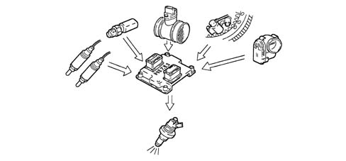
Fuel injection system
The essential conditions that must
always be met in the preparation of the air-fuel mixture for the
correct operation of controlled-ignition engines are mainly:
- the 'metering' (air/fuel ratio) should constantly be
kept as close as possible to the stoichiometric ratio, so as to
ensure the maximum conversion capacity for the catalytic converter
(max. efficiency).
- the 'homogeneity' of the mixture, consisting of petrol,
diffused as finely and evenly as possible in the air.
The information processed by the
control unit for controlling optimum metering is received in the
form of electrical signals emitted by:
- air flow meter and air temperature sensor, for the exact
quantity of intake air;
- rpm sensor which produces an alternating, single-phase
signal whose frequency indicates the engine rpm;
- accelerator pedal with throttle potentiometer, to recognize
the driver conditions requested;
- – coolant temperature sensor on the thermostat;
- Lambda probes for determining the oxygen
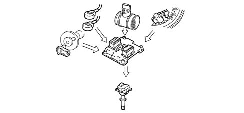
content in the exhaust gases.Ignition system
The ignition is of the inductive discharge
type, static advance type (i.e. without a high tension distributor) with
power modules located in the fuel injection control unit.The system has a single coil for
each plug (MONOCOIL); the advantages of this solution are:
- less electrical overload;
- guarantee of constant discharge at each spark plug.
Stored in the control unit, there is a map
containing the entire set of optimum ignition advance values (for the
cylinder at the power stroke) that the engine can adopt in relation
to the rpm and required engine load.The control unit corrects the advance
values mainly in accordance with:
- engine coolant temperature;
- intake air temperature;
- detonation.
The information the control unit
processes in order to drive the single coils is received in the
form of electrical signals emitted by:
- air flow meter and air temperature sensor, for the exact
quantity of intake air;
- rpm sensor which produces an alternating, single-phase
signal whose frequency indicates the engine rpm;
- detonation sensors (on the upper part of the cylinder
block/crankcase between the two heads) to recognize the cylinder
where detonation is occurring and correct the ignition advance;
- throttle potentiometer, to recognize the minimum, partial
and full load conditions;
- timing sensor.
The control unit uses the rpm signal to
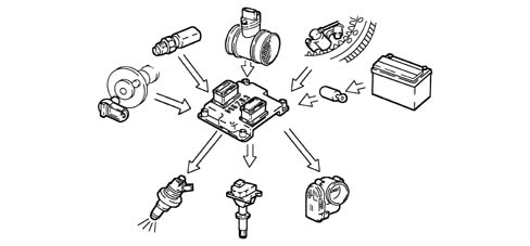
recognize any misfire which could damage the catalyzers.OPERATION
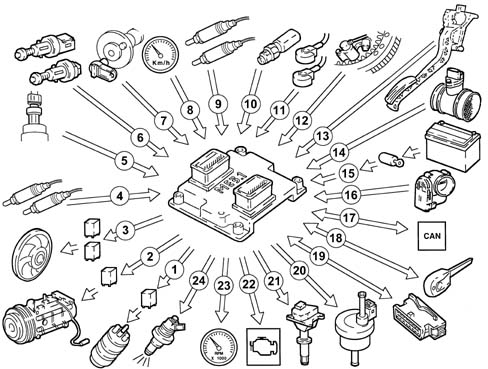
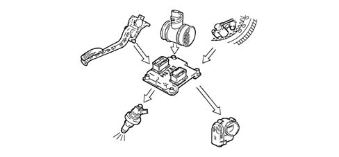
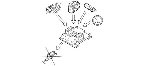
Diagram of input/output info to/from control
unit
1 - Electric fuel pump
2 - Air conditioner compressor
3 - Electric fan
4 - Lambda sensors upstream of the catalytic preconverters
5 - Quadrinary
6 - Brake - clutch pedal switch
7 - Timing sensor
8 - Speedometer
9 - Lambda sensors downstream of the catalytic converters
10 - Coolant temperature sensor
11 - Detonation sensors
12 - Rpm sensor
13 - Accelerator pedal with integrated potentiometer
14 - Air flow meter with air temperature sensor
15 - Battery
16 - Throttle body integral with D.V.L.;
17 - CAN line ( for communication with ABS/ASR control units
and automatic transmission)
18 - Alfa Romeo CODE
19 - Diagnostic socket
20 - Fuel vapour recirculation solenoid
21 - Ignition coils
22 - Engine Check warning light
23 - Rev counter
24 - Fuel injectors
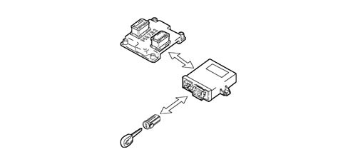
System operating modes
Self-learning
The control unit implements the self-learning
mode in the following conditions:
- installation of new injection control unit,
- installation of a new throttle body actuator integratd
with D.V.L.
- removing/refitting or replacement of rpm sensor/phonic
wheel, for recognizing misfire.
The learnt values of the throttle body integrated
with D.V.L. are preserved if the battery is disconnected.The learnt values of the phonic wheel for
recognizing misfire are instead lost.System self-adaptation
The control unit has a self-adaption function
which recognizes changes in the engine which occur as a result of
bedding-in and ageing processes of both components and the engine
itself.There are two adaptation functions according
to two intervention plans: minimum and usage.Self-testing
The control unit autodiagnostic system controls
the correct operation of the system and signals any faults by means
of an (MIL) warning light in the instrument panel which has a standardized
European colour and ideogram. This warning light signals both engine
management faults and problems detected by the EOBD strategies.The (MIL) warning light operating
logic is as follows:
- with the ignition key in the ON position, the warning
light comes on and remains on until the engine has been started
up. The control unit's self-test checks the signals coming from
the sensors, comparing them with the permitted limits:
Indication of starting faults:
- the failure of the warning light to go out after the
engine has been started up means that there is an error memorized
in the control unit.
Fault indication during operation
- the warning light flashing indicates possible damage
to the catalytic converter due to misfire.
- if the warning light comes on constantly, it indicates
the presence of engine management errors or EOBD RECOVERY diagnosis
errors
RECOVERYFrom time to time, the control unit defines
the type of recovery according to the components which are faulty. The
recovery parameters are managed by those components which are not
faulty.Recognition of the alfa romeo code
When the control unit receives the ignition
'ON' signal, it communicates with the Alfa Romeo CODE control unit
to obtain starting enablement.Check on cold starting
In cold starting conditions there
is a natural weakening of the mixture which causes poor evaporation
of the fuel at low temperatures:
- condensation of the fuel on the inner walls of the inlet
manifold;
- increased viscosity of the lubricant oil.
The electronic control unit recognizes
this condition and corrects the fuel injection time in accordance
with:
- coolant temperature;
- intake air temperature;
- battery voltage;
- engine rpm.
The ignition advance depends solely on the
engine rpm and the coolant temperature.During starting, the control unit controls
a first simultaneous injection for all the injectors (full-group
injection) and, after recognizing the timing of the cylinders, it
starts normal sequential phased operation.Whilst the engine is warming up, the control
unit operates the butterfly casing integrated with D.V.L. to regulate
the quantity of air required to ensure that the engine does not
cut out.The rotation speed decreases as the engine
temperature increases until the normal value is reached with the engine
at operating temperature.Check on combustion - lambda sensors
In EOBD systems the Lambda sensors, which
are all the same type, are located upstream of the catalyzer and downstream
of the catalyzer.The upstream sensors carry out the check
on the mixture strength known as the 1st loop (upstream sensors closed
loop). The sensors downstream of the catalyzer are used for the
catalyzer diagnosis and for finely modulating the 1st loop control
parameters.With this in mind, the adjustment of the
second loop is designed to recover both production differences and those
in the response of the upstream sensors which may occur as a result
of ageing and pollution.This control is known as the 2nd loop (downstream
sensors closed loop).Knock control
The control unit can delay the ignition
selectively at the cylinder required, according to the combination
of figures received from the detonation and timing sensors and:
- reduces the ignition advance in steps of 3° up to a
maximum of 9°
- updates the level to take into account background noise
and ageing of the engine.
During acceleration, the control unit uses
a higher threshold for the increased engine noise.When the detonation disappears, the control
unit increases the ignition advance in steps of 0.75° ??t??
?t ?s ??µp?ete?? ?e???e?ed.With the auto-adjustment function,
the control unit:
- memorizes the various advance reductions, continuously
repeated;
- adapts the map to the different engine conditions.
RECOVERYIn the case of fault with the timing sensor
or the detonation sensor or the injection control unit, the ignition is
delayed according to the engine temperature and speed. The maximum
ignition delay is always below 9° engine.Control of the mixture enrichment during acceleration
When there is a considerable acceleration
request, the control unit modifies the injection time and the position of
the butterfly.RECOVERYThe control unit replaces the signal coming
from the faulty air flow meter with a signal from the potentiometer built
into the throttle body actuator.Fuel cut-off with the accelerator pedal released
The control unit with:
- recognition of idle condition;
- engine speed above a certain threshold;
de-activates the fuel injection according
to the:
- engine rpm;
- engine temperature;
- vehicle speed.
Before reaching the idle condition, the
dynamics of the engine speed decrease are checked. If they exceed
a certain value, the fuel supply is partly reactivated on the basis
of a logic which makes provision for the 'gentle accompaniment'
of the engine whilst idling.Having reached the idle condition, the normal
functions are restored.Fuel vapour recovery
The (polluting) fuel vapours, collected
in an activated-charcoal filter (canister), are sent to the inlet
ducts to be burnt.This is achieved by a solenoid controlled
by the control unit which alternates phases when it is open (canister scrubbing
phase) with phases when it is closed (carburation factors learning
phase).During the open phases, the solenoid opening
duty cycle is regulated by the| ... DATA ERROR - CROPPED TEXT | Ошибка данных - Текст обрезан ... |
|---|