3239211 - Introduction - BRAKING SYSTEM
CONSTRUCTION FEATURES
All versions are equipped with Bosch 5.3 A.B.S. anti-lock brakes with four active sensors and four channels.The system control unit controls the EBD (Electronic Brake force Distribution) function to distribute the brake force between the front and rear axles.Disc brakes on all four wheels (self-ventilated on the high range).LUCAS floating aluminium caliper with automatic play take-upBOSCH 8' brake servo with additional chamber and 7/8' pumpMechanical type handbrake with twin cable.DESCRIPTION
General characteristics
The A.B.S. system consists of:
- an electronic control unit integrated in the electro-hydraulic control unit
- an electro-hydraulic control unit which modulates the braking pressure via eight solenoid valves, two for each wheel
- four 'active' type sensors which detect the angular rotation speed of the wheels.
Function check
Operating principleThe electronic control unit processes the signals coming from the active sensors and the brake light switch and implements the modulation of the brake fluid pressure in the following conditions:
- pressure increase stage
- pressure maintenance stage
- pressure reduction stage.
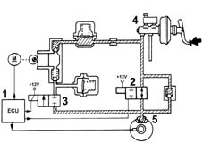
With the brake pedal pressure, the electronic control unit (1):
- does not supply the pressurizing solenoid valve (N.A.) (2)
- does not supply the discharge solenoid valve (N.C.) (3).
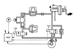
The electronic control unit (1):
- supplies the exhaust solenoid (N.O.) (2)
- does not supply the discharge solenoid valve (N.C.) (3).
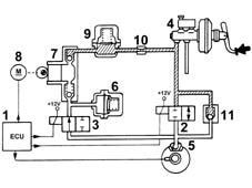
The electronic control unit (1):
- supplies the pressurizing solenoid valve (N.A.) (2)
- supplies the discharge solenoid valve (N.C.) (3).
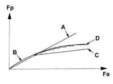
The EBD function controls the distribution of the brake force and therefore replaces the conventional mechanical load proportioning valve making it possible to:
- acts independently on the rear brake calipers
- improve the distribution of the brake forces
- intervene in an optimum manner in all load conditions (static or dynamic), driving conditions (in a straight line or round bends) and condition of the vehicle (tyres, brakes and suspension worn)
- implement a strategy which follows the ideal distribution curve.
A failure in the EBD function is signalled by the following warning lights coming on simultaneously:
- A.B.S. warning light
- insufficient brake fluid and/or handbrake applied warning light
It is therefore necessary:
- to avoid violent braking because the rear wheels may lock early
- to drive the vehicle extremely carefully to the nearest authorized workshop to have the system checked.
With the ignition key inserted, the safety circuit checks the following for 4 seconds:
- the operation of the electronic control unit
- it activates the solenoid valves to check their operation
- it operates the recovery pump to check its operation
- it checks the active sensor signals.
With the vehicle driving, the safety circuit behaves in the following way:
- it continuously compares the angular speed of the wheels with the reference speed calculated
- it checks the memory conditions
- govern operation of both relays
- it constantly checks the battery voltage
If the safety circuit has detected one or more irregularities with the system components during the checking stage it behaves in the following way:
- it switches off the A.B.S. system guaranteeing, however, the operation of the conventional braking system and EBD function.
- it signals the irregular condition to the driver by the warning light in the instrument panel coming on.