3239226 - Introduction - ELECTRICAL CIRCUIT FOR INSTRUMENTS/INDICATORS
The electrical system has been designed with the safety of the vehicle uppermost, to prevent the risk of fire and the other consequences of electrical malfunctions and to reduce defective connections thanks to the adoption of the latest generation connectors.The main solutions adopted are:
- Supplies protected by maxi fuses to interrupt the electrical system, in the case of a short circuit, just downstream of the battery.
- The only cables without maxi fuses (starter motor and alternator) are shielded and positioned in a safe place;
- The layout of the entire system is designed to optimize the risk of damage in the case of a failure or accident.
- There are special cables in the engine compartment which are resistant to high temperatures and also protected with sheaths or pipes.
- The connections are fitted with anti-slip devices on the terminals (secondary lock).
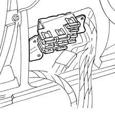
JUNCTION UNIT
This is located on the left side of the facia and is protected by a removable flap.Front view
Refer to the illustration
Rear view
Refer to the illustration
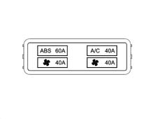
Fuses
The fuses are located on the front of the junction unit and are arranged as shown in the figure.
Maxifuse box
The main supply lines are protected by maxifuses, contained in two fuse boxes located near the battery and supplied directly from the latter.The two MAXIFUSE boxes contain fuses named according to the circuits protected, located as illustrated in the diagram:
- EFI: supply for fuses and relays for engine management
- IGN: ignition switch supply;
- J/B1 : supply for services through the junction unit fuses
- J/B2: supply for services through the junction unit fuses

- ABS: ABS supply;
- VENT: engine cooling fans supply;
- VENT: engine cooling fans supply;
- A/C: air conditioning system supply.
INTEGRATED SERVICES ELECTRONIC CONTROL UNIT
Presentation
A single, integrated electronic control unit located beneath the facia trim on the passenger side contains a series of functions and controls relating to electrical devices:
- door lock/release
- fog lamp control
- front electric window operation
- timed passenger compartment and boot lighting
- timed rear window and door mirror demist operation
Door lock/release
The control unit controls the simultaneous operation of the lock motors on all four doors upon a control:
- from the key;
- from the front door switches (knobs);
- issued via the remote control.
The control unit also carries out a series of safety checks:
- switch position is checked at the end of each operation. If this position does not agree with the action carried out (e.g. if a door is open), a repulsion command is issued, i.e. the opposite manoeuvre is carried out to realign all the locks.
- If the control unit detects several complete, consecutive lock/release manoeuvres - at least 8 within 20 seconds - the system cuts in to limit the manoeuvres: the system is inhibited in release position for 30 seconds.
- If battery voltage drops below 9 V during a lock/release operation, the system suspends the operation. If battery voltage is lower than 9 V at the outset, no command is issued.

Fog lamp control
The control unit controls front fog lamp activation, which can only take place with:
- the ignition in the ON position
- side lights on.

Fog lamp control
The control unit controls fog lamp activation, which can only take place with:
- the ignition in the ON position
- side lights on.
Operation of front windows
The control unit operates the front windows automatically, in accordance with the following system which depends on how the button is pressed:
- for the driver's window:
- the operation is manual (the glass goes up/down only when the button is pressed) when the button is held down for 60 to 300 milliseconds;
- the operation is instead automatic (the glass continues to go up/down to the end of travel, even if the button is released) when the button is held down for over 300 milliseconds;
- if the button is pressed again during movement of the glass, the glass is stopped instantly
- if the button is pressed for less than 60 milliseconds, it is ignored (it is considered to have been knocked accidentally)
- for the passenger's window:
- closing is only manual
- opening is the same as for the driver's window (automatic).
If there are faults on the electrical circuits, the control unit switches the system off temporarily, for example if:
- the motor control signals are interrupted or if the current uptake is below the usual values.
- there is a fault in the control buttons (short circuit, or buttons jammed in the pressed position).

Timed passenger compartment courtesy light
When any of the four doors is opened, all front and rear courtesy lights are operated for a timed period, in accordance with the following logic:
- timed period of 7 seconds when the locks are unlocked using the key or the remote control;
- a timed interval of 7 seconds when a previously opened door is closed again; timing is suspended when the ignition is turned on; this allows the driver to enter the car and insert the key in the ignition
- timed interval of 3 minutes if one of the doors is left open: this function prevents the battery going flat if the car is left with a door open
Timed boot lighting
When the boot is opened, a light is turned on for a timed interval of 20 minutes: this function ensures that the battery does not go flat if the car is left with the boot openTimer operation is suspended when the boot is closed
Timed demister operation (rear window and door mirrors)
The rear window heater element, door mirror demister coils and the windscreen heater element absorb a considerable amount of energy. They must therefore be turned off once they have been working for a certain period of time.The control unit supplies the heated rear window and door mirrors under the control of a timer. The procedure is as follows.The system is turned on with:
- the ignition in the ON position
- activation signal from the relevant button, located on the climate control system control panel (or from the air conditioner max defrosting function).
The power supply is also cut off under the following conditions:
- with the ignition in the OFF position
- deactivation signal from the relevant button (or the max. defrosting function);
- After 10 minutes of operation, if battery voltage drops below 11.6 V (the supply is restored if temperature rises to more than 13 V)

Control unit pin-out
Refer to the illustration
The fuse box contains up to eight maxifuses, named according to the circuits protected, located as illustrated in the diagram:
- J/B1 : supply for services through the junction unit fuses
- J/B2: supply for services through the junction unit fuses
- A/C: air conditioning system supply.
- EFI: supply for fuses and relays for engine management
- FAN 1: engine cooling fans supply
- FAN 2: engine cooling fans supply or F/P: automatic transmission supply (for cars with Q-System gearbox) or OIL: Selespeed system pump supply.
- O/A: automatic transmission supply (for Selespeed vehicles)
The fuse box also contains two 'MIDI' fuses, named according to the circuits protected, located as illustrated in the diagram:
- ABS: ABS supply;
- IGN: ignition switch supply
