3239194 - Introduction - ENGINE
GLOSSARY
GLOSSARY
Direct injection turbodiesel engine without ante-chambers, 5 cylinders in line, 2387 c.c., a counter-balance shaft, twin mass flywheel, two valves per cylinder, overhead camshaft, supercharged with a variable geometry turbocharger and intercooler, Bosch Common Rail EDC-15C electronic injection system.Description
General characteristics
The unit comprises the engine and all the systems required for its operation:
- fuel supply system
- air supply system
- engine cooling system
- exhaust system with catalytic converter
- oil vapour recirculation system
- E.G.R. exhaust gas recirculation system
The main features are:
- availability of high injection pressures (1350 bar)
- possibility of modulating these pressures between 150 bar and a maximum operating pressure of 1350 bar, irrespective of the engine rotation speed and load
- capacity of operating at high engine speeds (up to 6000 rpm)
- precision injection (advance and duration)
- reduction in consumption
- reduction in emissions.
The main functions of the system are basically as follows:
- control of the fuel temperature
- control of the engine coolant temperature
- control of the quantity of fuel injected
- control of the idle speed
- fuel cut-off during overrunning
- control of the cylinder balance during idling
- control of irregular operation
- control of exhaust fumes during acceleration
- control of exhaust gas recirculation (E.G.R.)
- control of maximum torque restriction
- control of maximum speed restriction
- control of the heater plugs
- control of engagement of climate control system (where fitted)
- control of auxiliary fuel pump
- control of the position of the cylinders
- control of the main injection advance and operation
- control of the closed loop injection pressure
- control of the electrical balance
- control of the supercharging pressure
- self diagnosis
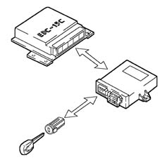
- connection to Alfa Romeo CODE (Immobilizer) control unit
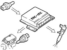
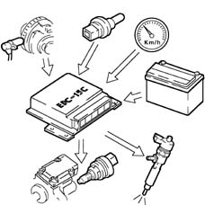
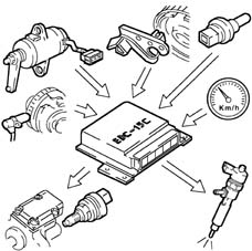
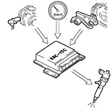
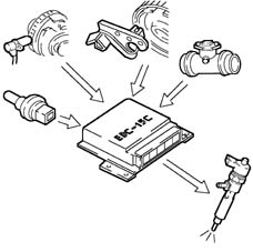
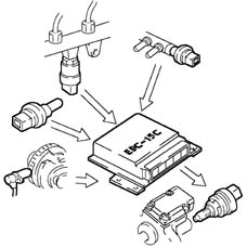
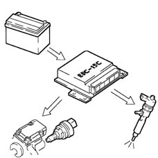
The control unit processes the following information to control the quantity of fuel to inject:
- engine rpm
- coolant temperature
- supercharging pressure
- air temperature
- intake air quantity
- battery voltage
- diesel pressure
- accelerator pedal position.
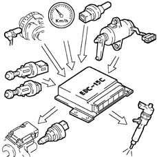
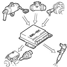
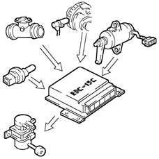
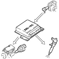
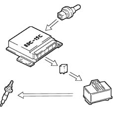
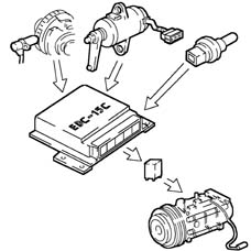
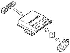
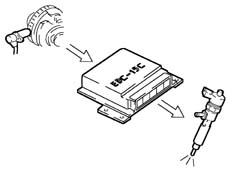
OPERATION
Diagram of input/output information to/from the control unit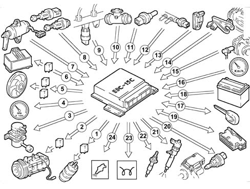
System operating modes
Self-diagnosisThe control unit's autodiagnosis checks the signals coming from the sensors, comparing them with the permitted limits:signalling of faults during starting:- warning light on for 4 seconds indicating test stage
- warning light off after 4 secs indicates no faults in components that could affect the values established in emission control regulations
- warning light on after 4 secs indicates fault
- warning light on indicates fault
- warning light off indicates no faults in components that could affect the values established in emission control regulations
- the control unit, from time to time, defines the type of recovery according to the faulty components
- the recovery parameters are managed by non-faulty components.
With the temperature of the engine coolant greater than 105° C, the control unit:
- reduces the quantity of fuel injected (reduces the engine power)
- operates the cooling fans
- lights up the coolant overheating warning light
On the basis of the signals coming from the sensors and the mapped values, the control unit:
- operates the pressure regulator
- varies the "pilot" injection time up to 3000 rpm
- varies the "main" injection time.

The control unit processes the signals coming from the various sensors and regulates the quantity of fuel injected:
- operates the pressure regulator
- varies the injector injection times.
When the accelerator pedal is released the control unit activates the following systems:
- supply to the fuel injectors cut off
- partial reactivation of the supply to the injectors before the idle speed is reached
- operates the fuel pressure regulator.
On the basis of the signals received from the sensors, the control unit controls the precision of the torque at idle speed:
- varies the quantity of fuel injected in the individual injectors (injection time).
The control unit processes the signals received from the various sensors and determines the quantity of fuel to be injected via:
- pressure regulator
- the opening time of the injectors.
When there is considerable acceleration, the control unit determines the optimum quantity of fuel to be injected, on the basis of the signals received from the flow meter and engine rpm sensor:
- operates the pressure regulator
- varies the injector injection time.
According to the number of revs, the control unit calculates the following from predefined maps:
- the torque limit
- the permissible fumes (limit).
It compares these minimum values and corrects them with other parameters:
- coolant temperature
- engine rpm
- vehicle speed

According to the number of revs, the control unit implements two intervention strategies:
- at 5000 rpm it cuts off the fuel, reducing the line pressure
- above 5400 rpm it deactivates the auxiliary pump and the injectors.
The injection control unit, during the following stages:
- start-up
- post-starting
The control unit operates the air conditioning compressor:
- switching it on/off when the relevant switch is pressed
- switching it off momentarily (for around 6 secs) if there is substantial acceleration or a request for maximum power.
Irrespective of the engine speed, the control unit:
- supplies the auxiliary fuel pump with the ignition key in the ON position
- excludes the auxiliary pump supply if the engine is not started up within several seconds.
According to the battery voltage, the control unit varies the idle speed:
- increases the injector injection time
- regulates the line pressure.
At the various engine operating speeds, the control unit processes the signal coming from the supercharging sensor and determines the quantity of fuel to be injected:
- operates the pressure regulator
- varies the injection time.