3239084 - 1016E10 single cylinder head, removed - overhaul
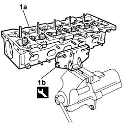
1. Position the upper cylinder head (1a) in the vice using the tool (1b). | Name | Country |
|---|---|---|
| 1b | Mount | 1.860.470.001 |


 | Measurement | Value | |
|---|---|---|---|
| - | Camshaft end float (mm) | 0.1 - 0.23 |
| Check that the tools, marked with the letter 'A', are correctly inserted in the housings in the camshafts. |
| Name | Country |
|---|---|---|
| 1b | Gauge | 1.870.896.900 |


| Name | Country |
|---|---|---|
| - | Gauge | 1.870.896.900 |


| Name | Country |
|---|---|---|
| - | Mount | 1.860.470.001 |
| Name | Country |
|---|---|---|
| 1b | Mount | 1.860.470.001 |
| Name | Country |
|---|---|---|
| 1 | Stand | 1.860.804.001 |

| Name | Country |
|---|---|---|
| 1a | Lever | 1.860.644.001 |
| Name | Country |
|---|---|---|
| 1b | Chamber | 1.870.890.000 |
| Name | Country |
|---|---|---|
| - | Pliers | 1.870.894.000 |

| Name | Country |
|---|---|---|
| - | Stand | 1.860.804.001 |
| Name | Country |
|---|---|---|
| - | Mount | 1.860.470.001 |
| Measurement | Value | |
|---|---|---|---|
| - | Cylinder head lower plane planarity (mm) | <0.1 |
| If the limit condition is reached (head gasket with 2 references before regrinding), the cylinder head lower plane cannot be reground. |
| Measurement | Value | |
|---|---|---|---|
| - | Permissible minimum height (mm) | 107.0 ± 0.05 |

| Measurement | Value | |
|---|---|---|---|
| - | Stem diameter (mm) | 5,982 ÷ 6,000 |
| Measurement | Value | |
|---|---|---|---|
| - | Stem diameter (mm) | 5,92 ÷ 5,990 |
| Measurement | Value | |
|---|---|---|---|
| - | Free length (mm) | 43.1 |
| Measurement | Value | |
|---|---|---|---|
| - | Length (mm) | 34 | |
| under load (daN) | 21.2 | ||
| Measurement | Value | |
|---|---|---|---|
| - | Length (mm) | 24.5 | |
| under load (daN) | 45 | ||
| Measurement | Value | |
|---|---|---|---|
| - | Diameter (mm) | Fifth pin | 43,000 ÷ 43,015 |
| First pin | 43,800 ÷ 43,815 | ||
| Fourth pin | 43,200 ÷ 43,215 | ||
| Second pin | 43,600 ÷ 43,615 | ||
| Third pin | 43,400 ÷ 43,415 | ||
| Measurement | Value | |
|---|---|---|---|
| - | Nominal cam lift (mm) | Exhaust | 8 |
| Inlet | 8 | ||
| Measurement | Value | |
|---|---|---|---|
| - | Diameter (mm) | Fifth support | 43,046 ÷ 43,071 |
| First support | 43,846 ÷ 43,871 | ||
| Fourth support | 43,246 ÷ 43,271 | ||
| Second support | 43,646 ÷ 43,671 | ||
| Third support | 43,446 ÷ 43,471 | ||

| Measurement | Value | |
|---|---|---|---|
| - | Outer diameter (mm) | Exhaust | 27,600 ÷ 27,611 |
| Inlet | 29,600 ÷ 29,611 | ||
| Measurement | Value | |
|---|---|---|---|
| - | Contact band angle with valve (Gradi) | Exhaust | 45° ± 0,1 |
| Inlet | 45°30' ± 1? | ||

| Measurement | Value | |
|---|---|---|---|
| 1a | Cylinder head surface recess (mm) | - |
| Name | Country |
|---|---|---|
| 1b | Dial gauge mounting | 1.870.404.001 |

| Name | Country |
|---|---|---|
| - | Mount | 1.860.470.001 |
| Name | Country |
|---|---|---|
| - | Stand | 1.860.804.001 |
| Name | Country |
|---|---|---|
| 1a | Drift | 1.871.000.600 |

| Name | Country |
|---|---|---|
| 3a | Lever | 1.860.644.001 |
| Name | Country |
|---|---|---|
| 3b | Chamber | 1.870.890.000 |

| Name | Country |
|---|---|---|
| - | Stand | 1.860.804.001 |
| Name | Country |
|---|---|---|
| - | Mount | 1.860.470.001 |
| Name | Country |
|---|---|---|
| 1b | Mount | 1.860.470.001 |

| Check that the tools, marked with the letter 'A', are correctly inserted in the housings in the camshafts. |
| Name | Country |
|---|---|---|
| 1 | Gauge | 1.870.896.900 |


| Name | Country |
|---|---|---|
| 1b | Fitting tool | 1.870.896.800 |


| Name | Country |
|---|---|---|
| 1b | Gauge | 1.870.896.900 |

| Name | Country |
|---|---|---|
| - | Mount | 1.860.470.001 |