3237654 - 1016C10 cylinder head - r + r and replace gasket
- 1092E10 counter-rotating shaft drive toothed belt - r + r . - 1092E10 counter-rotating shaft drive toothed belt - r + r . | Name | Connector |
|---|---|---|
| - | Battery | A1B |
 | Name | Country |
|---|---|---|
| 2 | Counter-torque | 1.860.898.000 |
| Name | Country |
|---|---|---|
| - | Counter-torque | 1.860.898.000 |
| Name | Connector |
|---|---|---|
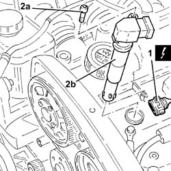
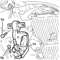
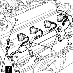
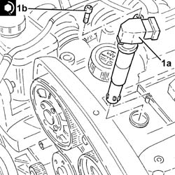
| 1 | Ignition coil | A30 |
| Name | Country |
|---|---|---|
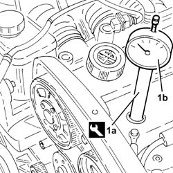
| 1a | Extension | 1.860.895.001 |
| If TDC is exceeded, do not turn backwards, but proceed by rotating the crankshaft through a further two revolutions in the same direction until the piston for cylinder no. 1 is at TDC. |
| Name | Country |
|---|---|---|
| - | Extension | 1.860.895.001 |
| Name | Connector |
|---|---|---|
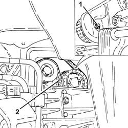
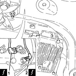
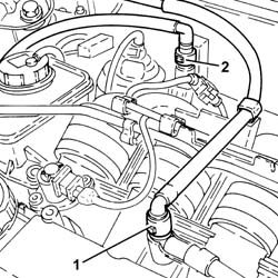
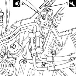
| 1 | Detonation sensor - 1 | K50 |
| Name | Connector |
|---|---|---|
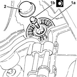
| 2 | Engine oil pressure sensor | K30 |
| Name | Connector |
|---|---|---|
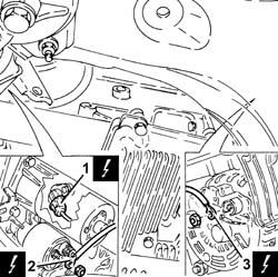
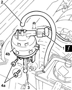
| 1 | Rpm sensor | K46 |
| Name | Connector |
|---|---|---|
| 2 | Starter' motor | A20 |
| Name | Connector |
|---|---|---|
| 3 | Alternator | A10 |
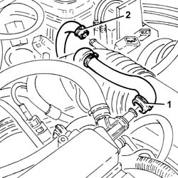
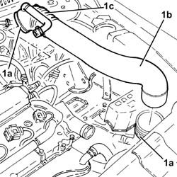
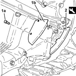
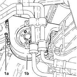
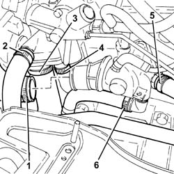
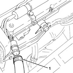
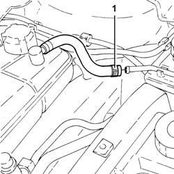
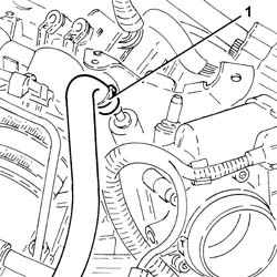
| Manually press the springs and remove the rapid attachment for the hose. |
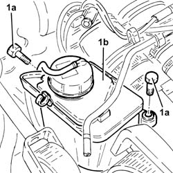
| Recover the coolant using a suitable container. |
| Name | Connector |
|---|---|---|
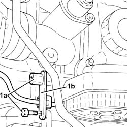
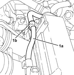
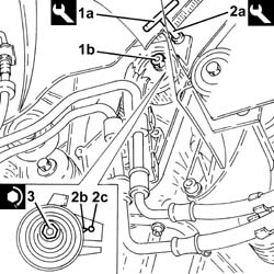
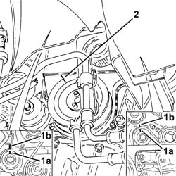
| 1b | Earth on engine | C40 |
| Name | Connector |
|---|---|---|
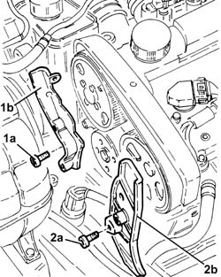
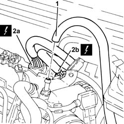
| 2a | Front/engine connection | D4A |
| Name | Connector |
|---|---|---|
| 2b | Front/engine connection | D4B |
| Name | Connector |
|---|---|---|
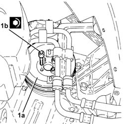
| 1 | Variable geometry control solenoid | L15 |
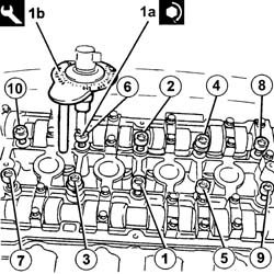
| To undo/tighten the cylinder head bolts, use the ordinary spanner USAG 233 1/2 S. |
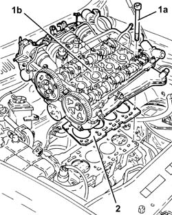
| Follow the order shown in the diagram for each tightening sequence. |
| To undo/tighten the cylinder head bolts, use the ordinary spanner USAG 233 1/2 S. |
 | Fastening | Component | Ø | Value(daNm) |
|---|---|---|---|---|
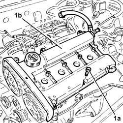
| 1a | Bolt | CYLINDER HEAD | M10 | (Engine crankcase side) 2.0 + 2.0 + 90° + 90° + 90 ° |
| Name | Country |
|---|---|---|
| 1b | Protractor | 1.860.942.000 |
| Name | Country |
|---|---|---|
| 1a | Extension | 1.860.895.001 |
| If T.D.C. is exceeded, do not turn backwards, but proceed by rotating the crankshaft through a further two revolutions in the same direction until the piston for cylinder no. 1 is at T.D.C. |
| Name | Country |
|---|---|---|
| 1b | Counter-torque | 1.860.856.001 |
| Name | Country |
|---|---|---|
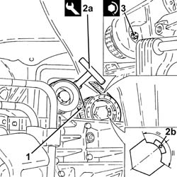
| 2b | Spanner for camshaft pulley rotation | 1.860.831.002 |
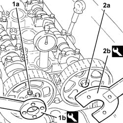
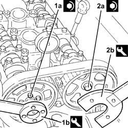
| Check that the camshaft cam profile matches the tool correctly. |
| Name | Country |
|---|---|---|
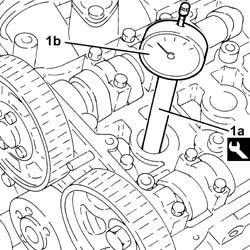
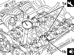
| 1a | Gauge | 1.870.859.000 |
| Fastening | Component | Ø | Value(daNm) |
|---|---|---|---|---|
| 1b | Bolt | ENGINE TIMING ADJUSTMENT TEMPLATES | M7 | (Cylinder head side) 1.0 |
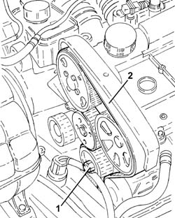
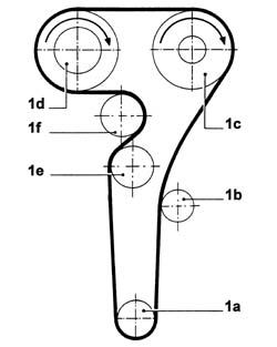
| Before fitting the belt on the exhaust side driven pulley, rotate it in a clockwise direction (see diagram) until the end of travel position. |
| Before fitting the belt on the inlet side driven pulley, rotate it in a clockwise direction (see diagram) until the end of travel position. |
| When fitting, ensure that the arrow stamped on the belt is facing in the direction of engine rotation (clockwise - timing side). |
| Name | Country |
|---|---|---|
| 1 | Key | 1.822.149.000 |
| Fastening | Component | Ø | Value(daNm) |
|---|---|---|---|---|
| 2 | Nut | MOBILE TIMING TENSIONER | M8 | 2.3 ÷ 2.8 |
| Fastening | Component | Ø | Value(daNm) |
|---|---|---|---|---|
| 1a | Bolt | TIMING GEAR DRIVEN PULLEYS | M6 | (Inlet camshaft side) 0.8 ÷ 1.0 |
| Name | Country |
|---|---|---|
| 1b | Counter-torque | 1.860.856.001 |
| Fastening | Component | Ø | Value(daNm) |
|---|---|---|---|---|
| 2a | Bolt | TIMING GEAR DRIVEN PULLEYS | M12 | (Exhaust camshaft side) 10.8÷13.2 |
| Name | Country |
|---|---|---|
| 2b | Spanner for camshaft pulley rotation | 1.860.831.002 |
| Name | Country |
|---|---|---|
| - | Gauge | 1.870.859.000 |
| Fastening | Component | Ø | Value(daNm) |
|---|---|---|---|---|
| - | Bolt | CAMSHAFT SUPPORTS | M7 | (Cylinder head side) 1.4 ÷ 1.7 |
| Name | Country |
|---|---|---|
| 1a | Key | 1.822.149.000 |
| Name | Country |
|---|---|---|
| 2a | Key | 1.822.149.000 |
| Fastening | Component | Ø | Value(daNm) |
|---|---|---|---|---|
| 3 | Nut | MOBILE TIMING TENSIONER | M8 | 2.3 ÷ 2.8 |
| Name | Country |
|---|---|---|
| - | Gauge | 1.870.859.000 |
| Name | Country |
|---|---|---|
| - | Extension | 1.860.895.001 |
| Fastening | Component | Ø | Value(daNm) |
|---|---|---|---|---|
| - | - | SPARK PLUGS | M14 | (Cylinder head side) 2.4 ÷ 3.0 |
| Fastening | Component | Ø | Value(daNm) |
|---|---|---|---|---|
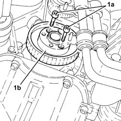
| 1b | Bolt | COUNTER-ROTATING SHAFT DRIVE PULLEY | M6 | (Timing drive pulley side.) 0.8÷1.0 |
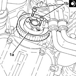
| Name | Country |
|---|---|---|
| 2a | Key | 1.822.154.000 |
| Fastening | Component | Ø | Value(daNm) |
|---|---|---|---|---|
| 3 | Nut | COUNTER-ROTATING SHAFT BELT TENSIONER | M6 | (.Left. counter balance shaft front) cover side 0.8÷1.0 |
| Fastening | Component | Ø | Value(daNm) |
|---|---|---|---|---|
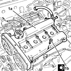
| 1b | Bolt | CAM COVER | M6 | (Cylinder head side) 0.8 ÷ 1.0 |
| Fastening | Component | Ø | Value(daNm) |
|---|---|---|---|---|
| 1b | Bolt | IGNITION COIL/REEL | M6 | (Tappet cover side) 0.8 ÷ 1.0 |
| Fastening | Component | Ø | Value(daNm) |
|---|---|---|---|---|
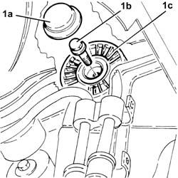
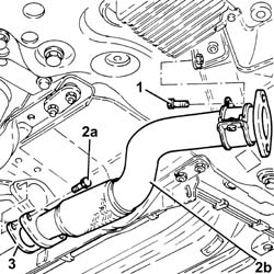
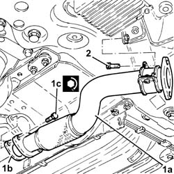
| 1c | Bolt | RIGID EXHAUST PIPE | M10 | (Front silencer side) 5.9 ÷ 7.2 |
| Fastening | Component | Ø | Value(daNm) |
|---|---|---|---|---|
| 1b | Bolt | FIXED SINGLE SERVICE BELT TENSIONER | M8 | 2.2 ÷ 2.8 |
| Name | Country |
|---|---|---|
| - | Counter-torque | 1.860.898.000 |
| Fastening | Component | Ø | Value(daNm) |
|---|---|---|---|---|
| 1b | Bolt | CRANKSHAFT PULLEY | M8 | 2.3 ÷ 2.8 |
| Name | Country |
|---|---|---|
| - | Counter-torque | 1.860.898.000 |