3239084 - 1016E10 single cylinder head, removed - overhaul
 | Name | Country |
|---|---|---|
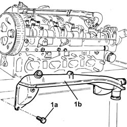
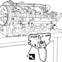
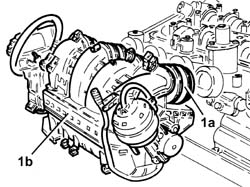
| 1 | Mount | 1.860.470.001 |
 | Name | Connector |
|---|---|---|
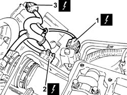
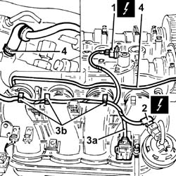
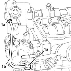
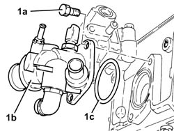
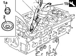
| 1 | Engine temperature sender unit | K36 |
| Name | Connector |
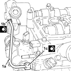
|---|---|---|
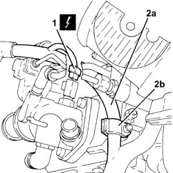
| 1 | Fuel pressure regulator | N77 |
| Name | Connector |
|---|---|---|
| 2 | Fuel pressure sensor | K83 |
| Name | Connector |
|---|---|---|
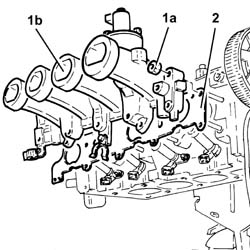
| 3 | Throttle body actuator | N75 |
| Name | Connector |
|---|---|---|
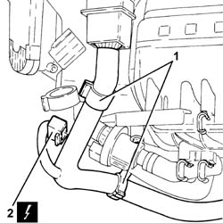
| 2 | Variable geometry control solenoid | L15 |
| Name | Connector |
|---|---|---|
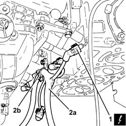
| 2 | Fuel vapour recovery solenoid | L10 |
| Name | Connector |
|---|---|---|
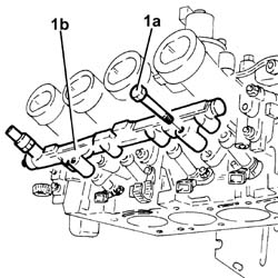
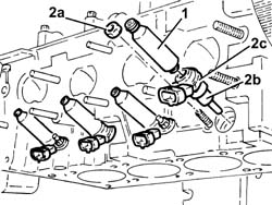
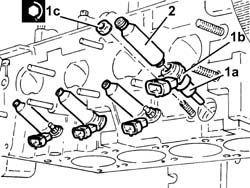
| 1 | Injector | N70 |
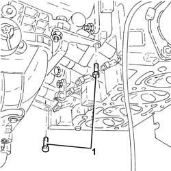
| The high pressure fuel pipe must be replaced at each reassembly. |
| Name | Country |
|---|---|---|
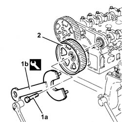
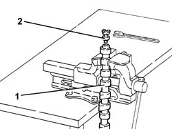
| 1b | Spanner for camshaft pulley rotation | 1.860.831.002 |
| Name | Country |
|---|---|---|
| 1b | Counter-torque | 1.860.856.001 |
 | Measurement | Value | |
|---|---|---|---|
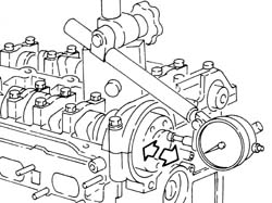
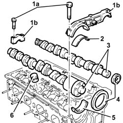
| - | Camshaft end float (mm) | 0.10 ÷ 0.23 |
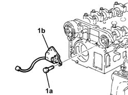
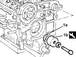
| The front cap has silicone sealant, so a plastic hammer should be used for its removal. |
| Name | Country |
|---|---|---|
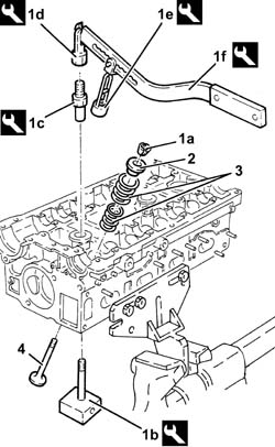
| 1b | Valve supports | 1.820.011.000 |
| Name | Country |
|---|---|---|
| 1c | Special nut | 1.820.049.000 |
| Name | Country |
|---|---|---|
| 1d | Mount | 1.821.124.000 |
| Name | Country |
|---|---|---|
| 1e | Chamber | 1.821.205.000 |
| Name | Country |
|---|---|---|
| 1f | Lever | 1.821.058.000 |
| Name | Country |
|---|---|---|
| 1b | Extractor | 1.860.989.000 |
| Measurement | Value | |
|---|---|---|---|
| - | Cylinder head lower plane planarity (mm) | 0.1 |
| Measurement | Value | |
|---|---|---|---|
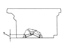
| 1 | Combustion chamber minimum permissible height (mm) | 12.8 ÷ 13.2 |
| Measurement | Value | |
|---|---|---|---|
| - | Combustion chamber volume (c.c.) | 38.2 |
| Measurement | Value | |
|---|---|---|---|
| - | Valve stem diameter (mm) | Exhaust | 6.960 ÷ 6.975 |
| Inlet | 6.975 ÷ 6.990 | ||
| Measurement | Value | |
|---|---|---|---|
| - | Valve head diameter (mm) | Exhaust | 28.2 |
| Intake | 33.7 | ||
| Measurement | Value | |
|---|---|---|---|
| - | Valve contact band taper (-) | 45° 30' |
| Measurement | Value | |
|---|---|---|---|
| - | Hydraulic tappeter outer diameter (mm) | 32.959 ÷ 32.975 |
| Measurement | Value | |
|---|---|---|---|
| - | Diameter of hydraulic tappet seats (mm) | 33.000 ÷ 33.025 |
| Measurement | Value | |
|---|---|---|---|
| - | Valve spring length released (mm) | External | 46.0 |
| Internal | 39.0 | ||
| Measurement | Value | |
|---|---|---|---|
| - | Outer valve spring height (mm) | 35.0 | |
| Check load (daN) | 25.0 ÷ 27.4 | ||
| Measurement | Value | |
|---|---|---|---|
| - | Outer valve spring height (mm) | 24.4 | |
| Check load (daN) | 49.4 ÷ 53.4 | ||
| Measurement | Value | |
|---|---|---|---|
| - | Inner valve spring height (mm) | 28.7 | |
| Check load (daN) | 11.6 ÷ 12.6 | ||
| Measurement | Value | |
|---|---|---|---|
| - | Inner valve spring height (mm) | 18.1 | |
| Check load (daN) | 23.6 ÷ 25.6 | ||
| Measurement | Value | |
|---|---|---|---|
| - | Camshaft bearing diameter (mm) | 26.000 ÷ 26.015 |
| Measurement | Value | |
|---|---|---|---|
| - | Camshaft nominal cam lift (mm) | Exhaust | 10.2 |
| Intake | 10.6 | ||
 | Fastening | Component | Ø | Value(daNm) |
|---|---|---|---|---|
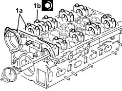
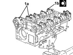
| 1b | Bolt | CAMSHAFT SUPPORTS | M7 | (Cylinder head side) 1.4 ÷ 1.7 |
| Measurement | Value | |
|---|---|---|---|
| - | Camshaft bearing diameter (mm) | 26.045 - 26.070 |
| Measurement | Value | |
|---|---|---|---|
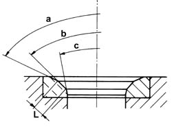
| - | Angle"a" valve seat upper band (-) | 150° |
| Measurement | Value | |
|---|---|---|---|
| - | Angle "b" contact band with valves (-) | 90° ± 10? |
| Measurement | Value | |
|---|---|---|---|
| - | Angle "c" valve seat lower band (-) | 30° |
| Measurement | Value | |
|---|---|---|---|
| - | Width "L" contact band with valves (mm) | Exhaust | 1.0 |
| Intake | 0.8 | ||
| Name | Country |
|---|---|---|
| - | Mount | 1.860.470.001 |
| Name | Country |
|---|---|---|
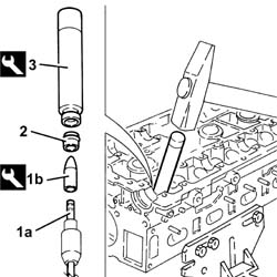
| 1b | Drift | 1.860.814.001 |
| Name | Country |
|---|---|---|
| 3 | Fitting tool | 1.860.812.000 |
| Name | Country |
|---|---|---|
| 1b | Valve supports | 1.820.011.000 |
| Name | Country |
|---|---|---|
| 1c | Special nut | 1.820.049.000 |
| Name | Country |
|---|---|---|
| 4b | Mount | 1.821.124.000 |
| Name | Country |
|---|---|---|
| 4c | Chamber | 1.821.205.000 |
| Name | Country |
|---|---|---|
| 4d | Lever | 1.821.058.000 |

| Fastening | Component | Ø | Value(daNm) |
|---|---|---|---|---|
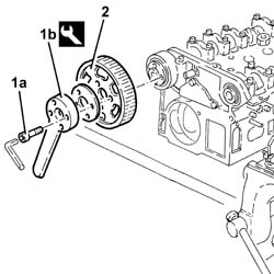
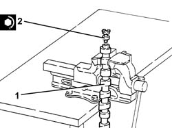
| 2 | - | PRESSURE PUMP DRIVE SPIGOT | M12 | (Exhaust camshaft side) 8.2 ÷ 10.0 |
| Apply silicone sealant between the front cap and the cylinder head. |
| Fastening | Component | Ø | Value(daNm) |
|---|---|---|---|---|
| 1b | Bolt | CAMSHAFT SUPPORTS | M7 | (Cylinder head side) 1.4 ÷ 1.7 |
| Name | Country |
|---|---|---|
| 1b | Fitting tool | 1.821.228.000 |
| Name | Country |
|---|---|---|
| 1b | Fitting tool | 1.821.252.000 |
| Fastening | Component | Ø | Value(daNm) |
|---|---|---|---|---|
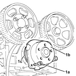
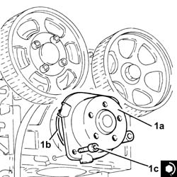
| 1c | Bolt | COOLANT PUMP | M8 | (Cylinder head side) 2.3 ÷ 2.8 |
| Fastening | Component | Ø | Value(daNm) |
|---|---|---|---|---|
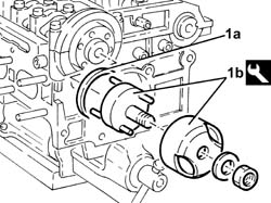
| 1c | Bolt | HIGH PRESSURE FUEL PUMP | M6 | (Cylinder head side) 0.8 ÷ 1.0 |
| Fastening | Component | Ø | Value(daNm) |
|---|---|---|---|---|
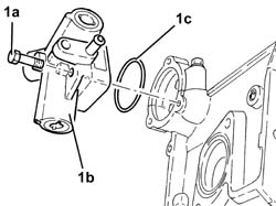
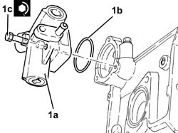
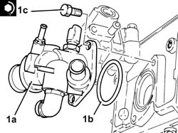
| 1c | Bolt | THERMOSTAT | M8 | (Cylinder head side) 2.3 ÷ 2.8 |
| Fastening | Component | Ø | Value(daNm) |
|---|---|---|---|---|
| 1c | Self-locking nut | INJECTORS | M6 | (Intake manifold side) 0.5 ÷ 0.6 |
| Fastening | Component | Ø | Value(daNm) |
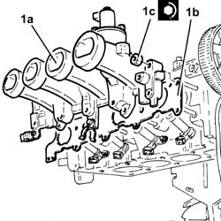
|---|---|---|---|---|
| 1c | Nut | INLET MANIFOLD | M8 | (Cylinder head side) 2.3 ÷ 2.8 |
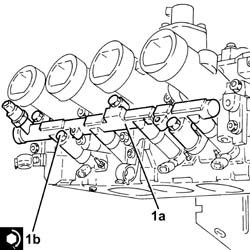
| Fastening | Component | Ø | Value(daNm) |
|---|---|---|---|---|
| 1b | Bolt | FUEL MANIFOLD | M9 | (Intake manifold side) 3.9 ÷ 4.7 |
| Fastening | Component | Ø | Value(daNm) |
|---|---|---|---|---|
| 1b | Connector | FUEL HIGH PRESSURE PIPE | M10 | (High pressure pump side) 1.2 ÷ 1.6 |
| Fastening | Component | Ø | Value(daNm) |
|---|---|---|---|---|
| 1c | Connector | FUEL HIGH PRESSURE PIPE | M12 | (Fuel manifold pipe side) 2.0 ÷ 2.4 |
| Name | Country |
|---|---|---|
| - | Mount | 1.860.470.001 |