125000871 - 1004E20 ENGINE - DISMANTLE AND RE-BUILD FOLLOWING OPERATION 1004E10 - WASH AND CHECK DISMANTLED PARTS - RE-FIT CYLINDER HEAD AND OIL SUMP - DOES NOT INCLUDE REPAIRS TO CYLINDER HEAD AND AUXILIARY UNIT

Removing
(
Refitting
)
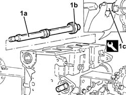
1. Undo bolts (1a) and remove the timing side engine support (1b).2. Undo the bolts (2a) and remove the counter-balance shaft toothed belt drive pulley (2b).
1. Fit the flywheel lock. | Description | Code |
|---|
| 1 | Counter-torque | 1.860.846.001 |
1. Undo the bolt (1a) (left hand thread) and remove the toothed drive pulley (1b).
1. Undo the bolts (1a) and remove the engine flywheel (1b). | The bolts fixing the flywheel have been treated with a special agent; therefore they should be replaced each time they are removed. |
2. Remove the flywheel lock. | Description | Code |
|---|
| 2 | Counter-torque | 1.860.846.001 |
1. Undo the bolts (1a) and remove the flywheel guard (1b).
1. Unscrew the bolt securing the engine oil intake duct to the main bearing cap.
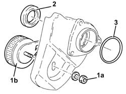
1. Undo the bolts (1a) and remove the engine block front cover (1b) with the built-in oil pump complete with intake (1c), engine oil heat exchanger (1d) and engine oil filter (1e).2. Remove the gasket.
1. Position the crankcase front cover assembly in the vice fitted with protective jaws.2. Undo the bolts (2a) and remove the engine oil intake duct (2b).3. Remove the gasket.4. Remove the engine oil filter using a suitable tool.5. Undo the pin (5a) and remove the engine oil heat exchanger (5b) complete with pipes (5c).6. Remove the gasket.7. Release the oil seal from the crankcase front cover. | Take care not to damage the oil seal seat during its removal. |
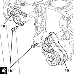
Proceed with the removal Op. 1084B18 ENGINE OIL PUMP, REMOVED - CHECK AT BENCH1. Undo the bolts (1a) and remove the support (1b) complete with timing belt moving tensioner (1c) and timing belt fixed tensioner (1d).
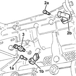
1. Undo the bolt (1a) and remove the detonation sensor (1b).2. Undo the bolt (2a) and remove the rpm sensor (2b).3. Undo and remove the engine oil pressure warning light switch.
1. Fit the tool for rotating the crankshaft. | Description | Code |
|---|
| 1 | Flange | 1.820.618.000 |
Rotate the crankshaft using the tool fitted previously until cylinders 1 and 4 are at B.D.C.1. Undo the bolts (1a) and remove the connecting rod caps (1b) complete with half-bearings (1c) for cylinders 1 and 4.2. Remove the cylinder 1 and 4 piston-connecting rod assemblies (2a) complete with half-bearings (2b)Carry out the same operations to remove the connecting rod half-bearings for the remaining cylinders.3. Remove the tool for rotating the crankshaft. | Description | Code |
|---|
| 3 | Flange | 1.820.618.000 |
Proceed with the removal Op. 1028H60 PISTON, PIN SET - REPLACE.1. Undo the bolts (1a) and remove the crankcase rear cover with the oil seal (1b) incorporated.
Check that the crankshaft endfloat corresponds to the recommended figures using a magnetic base and dial gauge. | Measurement | | Value |
|---|
| - | Crankshaft endfloat (mm) | | 0.059 ÷ 0.221 |
1. Undo the bolts (1a) and remove the main journal caps (1b) complete with half-bearings (1c).2. Remove the crankshaft.3. Remove the main journal half-bearings.4. Remove the thrust washers.
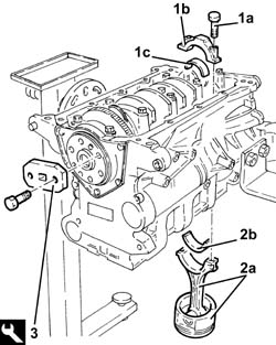
1. Undo the bolts (1a) and remove the engine oil jets (1b) from the crankcase.
Rotate the engine through 180° on the overhaul stand.1. Undo the bolts (1a) for the counter-balance shaft drive pullies using the tool (1b) for counter-torque. | Description | Code |
|---|
| 1b | Counter-torque | 1.820.286.000 |
1. Remove the counter-balance shaft drive pullies.2. Undo the bolts (2a) and remove the inlet side counter-balance shaft front cover (2b) complete with oil seal (2c) and O-ring.3. Undo the bolts (3a) and remove the exhaust side counter-balance shaft front cover (3) complete with counter-balance shaft toothed drive pulley tensioner (3c), oil seal (3d) and O-ring.
1. Completely undo the nut (1a) loosened previously and remove the counter-balance shaft toothed drive belt tensioner (1d) from the cover.2. Release and remove the oil seals from the counter-balance shaft front covers.3. Remove the O-rings from the counter-balance shaft covers.
1. Remove the spacers (1a) and the O-rings (1b) from the counter-balance shafts.2. Remove the counter-balance shafts (2a) complete with rear bearings (2b) using a suitable drift (2c).3. Keep the counter-balance shaft rear plugs.
1. Remove the counter-balance shaft front bearings (1a) from the crankcase using tools (1b) and (1c). | Description | Code |
|---|
| 1b | Extractor | 1.840.207.815 |
| Description | Code |
|---|
| 1c | Mallet | 1.847.017.002 |
Position the counter-balance shaft in a vice fitted with protective jaws.1. Remove the counter-balance shaft rear bearing circlip.2. Remove the counter-balance shaft rear bearing (2a) using a suitable drift (2b).Repeat the above operations for the remaining counter-balance shaft.
1. Remove the anti-reflux valve from the vertical duct in the engine block supplying oil to the cylinder head.
Drill and remove the water/oil sealing plugs from the crankcase to allow for washing the ducts.
Refitting
(
Removing
)
Wash all the dismantled components thoroughly.Clean any sealant residues from the mating surfaces between the engine oil sump and the engine block.Place the new crankcase water/oil sealing plugs back in their housings using suitable fitting tools.Place the anti-reflux valve in its housing in the vertical duct in the engine block supplying oil to the cylinder head.Lubricate all the mechanical components with engine oil.Visually check that the cylinder head support surface does not have cracks or superficial grooves.Check that the planarity of the cylinder head support surface corresponds to the recommended figure; if this is not the case, regrind the cylinder head support surface. | Measurement | | Value |
|---|
| - | Cylinder head support surface flatness (mm) | | < 0.1 |
Check that the internal diameter of the cylinder liners is within the recommended limits. | Measurement | | Value |
|---|
| - | Cylinder liner diameter (mm) | Category A | 83.000 ÷ 83.010 |
| Category B | 83.010 ÷ 83.020 |
| Category C | 83.020 ÷ 83.030 |
Check that the taper of the cylinder liners is within the recommended limits. | Measurement | | Value |
|---|
| - | Maximum permitted cylinder liner taper (mm) | | < 0.010 |
Check that the ovality of the cylinder liners is within the recommended limits. | Measurement | | Value |
|---|
| - | Maximum permitted cylinder liner ovality (mm) | | < 0.005 |
If the cylinder bore measurements are not within the recommended limits, ream the cylinder bores following the recommended oversizes. | In the case of reaming, all the cylinder bores must have the same oversize. |
| Measurement | | Value |
|---|
| - | Cylinder liner diameter oversize (mm) | | 0.1 |
Check that the diameter of the main journals is within specified limits. | Measurement | | Value |
|---|
| - | Main journal diameter (mm) | Category A | 52.982 ÷ 52.988 |
| Category B | 52.988 ÷ 52.994 |
| Category C | 52.994 ÷ 53.000 |
If the diameter of the main journals is not correct, they should be reground to the recommended undersize. | If undersizes of more than 0.127 are required by the regrinding, then the crankshaft must be replaced. |
| Measurement | | Value |
|---|
| - | Main journal diameter undersize (mm) | | 0.127 |
Check that the diameter of the crankpins corresponds to the recommended figures. | Measurement | | Value |
|---|
| - | Crankpin diameter (mm) | Category A | 50.787 ÷ 50.793 |
| Category B | 50.793 ÷ 50.799 |
| Category C | 50.799 ÷ 50.805 |
If the diameter of the crankpins is not correct, they should be reground to the recommended undersize. | If undersizes of more than 0.127 are required by the regrinding, then the crankshaft must be replaced. |
| Measurement | | Value |
|---|
| - | Crankpin diameter undersize (mm) | | 0.127 |
Check that the small end bush internal diameter is within the recommended limits; if not, replace the worn small end bush. Op. 1028H58 CONNECTING ROD SMALL END BUSH - REPLACE. | Measurement | | Value |
|---|
| - | Small end bush inner diameter (reaming) (mm) | | 20.006 ÷ 20.012 |
Check the matching between the gudgeon pin and the piston housing: it should be possible to insert the gudgeon pin by applying gentle pressure and it should not slip out.Check that the outer diameter of the gudgeon pins is within the recommended limits; if not, replace the worn gudgeon pins. | Measurement | | Value |
|---|
| - | Piston pin outer diameter (mm) | | 19.996 ÷ 20.000 |
Fit the piston rings in the cylinder bore and check that the opening between the ends is within the recommended values; if this is not the case, replace the circlips. | Measurement | | Value |
|---|
| - | Piston seal gap (mm) | 1st Ring | 0.25 ÷ 0.50 |
| 2nd ring | 0.25 ÷ 0.50 |
| Measurement | | Value |
|---|
| - | Piston oil scraper ring gap (mm) | | 0.25 ÷ 0.45 |
The size of the seals is given below. | Measurement | | Value |
|---|
| - | Piston seal size (mm) | 1st Ring | 1.19 |
| 2nd ring | 1.5 |
| Measurement | | Value |
|---|
| - | Piston oil scraper ring size (mm) | | 2.0 |
The oil scraper rings are also supplied in the following oversizes. | Measurement | | Value |
|---|
| - | Piston ring size oversize (mm) | | 0.1 |
Check that the outer diameter of the pistons corresponds to the recommended figures; if not, replace the piston complete with piston rings and gudgeon pin. | The outer diameter of the pistons should be measured perpendicular to the gudgeon pin axis and 10.0 mm from the lower edge of the skirt. |
| Measurement | | Value |
|---|
| - | Piston outer diameter (mm) | Category A | 82.952 ÷ 82.962 |
| Category B | 82.959 ÷ 82.971 |
| Category C | 82.969 ÷ 82.978 |
The clearance between the pistons and the liner/bore is given below.| ... DATA ERROR - CROPPED TEXT | Ошибка данных - Текст обрезан ... |
|---|
1 - Crankpin identification numerical code: the left number refers to the first timing side bearing; the final "N" is an insignificant code for 4 cylinder engines.2 - Main journal identification numerical code: the first number refers to the first timing side bearing; the final "N" is an insignificant code for 4 cylinder engines.3 - Series of numbers (if present), in groups of two digits, which indicate the dimensions (thousandth part) of the main journals: the first two numbers on the left refer to the first timing side bearing. | Only use the codes that relate to the key, all other codes on the flywheel should not be used. |
For the identification of the main journal grade, refer to the numerical code for reference 2 in the key.In the case of the example, the numbers 11111N indicate that all five bearings are Grade A (red) as indicated below.A further method for identifying the grade of the bearings is to read reference 3 (if present) in the diagram.In the case of the example, the number 84 (first on the left) corresponds to the dimensions 52.984 for the first timing side bearing which identifies Grade A (red); the same method should be applied for other groups of two digits for the same reference 3 (87 -85 -85 -84).MAIN JOURNAL IDENTIFICATIONMain journal grade A (normal), diameter 52.982.52.988 mm, RED paint mark, numerical code 1 (82 88)*Main journal grade B (normal), diameter 52.982.52.994 mm, BLUE paint mark, numerical code 2 (88 94)*Main journal grade C (normal), diameter 52.994.53.000 mm, YELLOW paint mark, numerical code 3 (94 00)*Main journal grade D (0.127 mm undersize), diameter 52.885.52.861 mm, BROWN paint mark, numerical code 6 (55 61)*Main journal grade E (0.127 mm undersize), diameter 52.861.52.867 mm, GREEN paint mark, numerical code 7 (61 67)*Main journal grade F (0.127 mm undersize), diameter 52.867.52.873 mm, BLACK paint mark, numerical code 8 (67 73)*(*): Last two numbers (thousandth part) of the main journal dimensions.- In the case of the usage of a crankshaft where the maximum undersize for the bearings is 0.127 mm through grindings, the grade should be selected through the measurement of the diameter of the bearing using the above as a reference.- Having defined the grade and the colour of each new or reground crankshaft bearings, it is necessary to select the thickness of the half-bearings that should be the same colour as the corresponding bearing; the pair of half-bearings required can be ordered from the Parts Dept. by quoting the order no.The above is designed to guarantee the optimum operational clearances for all the bearings.Lastly, we wish to point out that,in general, the clearance between the main journal and the half-bearing, produced through the selection method described above, should be 0.031 - 0.051 mm; this figure can be measured, as part of the final check, using the calibrated wire (Plastic Gauge) following the instructions described below.Place the half-bearings back in their housings in the engine block as described previously. | Great care should be taken over cleanliness when refitting. |
1. Place the crankshaft in its housing.2. Fit the calibrated wire (plastigage) for measuring the bearing clearance.
1. Place the bearing cap (1a), complete with half-bearing, back in its housing and secure it tightening the bolts (1b) to the recommended torque. | The bearing caps are marked with progressively numbered references (from zero to four starting from the front of the engine) which define the fitting position. |
| The safety references on the cylinder block/crankcase and on the bearing caps should be on the same side. |
| Fastening | Component | Ø | Value(daNm) |
|---|
| 1b | Bolt | MAIN BEARING CAPS | M12 | 2.4 ÷ 2.6 + 100? |
2. Use the tool for the angular tightening of the bearing cap bolts. | Description | Code |
|---|
| 2 | Torque wrench | 1.860.942.000 |
1. Remove the bearing cap fitted previously and, using a suitable graduated measuring instrument (1a), measure the clearance shown by the calibrated wire (1b). | Measure the clearance for all the bearings taking care to take the measurements one at a time without moving the crankshaft at any time. |
| Measurement | | Value |
|---|
| 1 | Main journal/half-bearing clearance (mm) | | 0.031 ÷ 0.051 |
| If the figure measured is outside of the tolerance, replace the half-bearings with ones of the correct size and category. |
Place the half-bearings in their seats.Place the thrust washers (with the size depending on the crankshaft endfloat measured during the dismantling) in their housings in the third bearing support. | The thrust washer lubrication ducts should be facing the crankshaft thrust washers. |
Place the crankshaft in its housing.1. Place the bearing caps (1a), complete with half-bearing, back in their housings and secure them tightening the bolts (1b) to the recommended torque. | The bearing caps are marked with progressively numbered references (from zero to four starting from the front of the engine) which define the fitting position. |
| The safety references on the cylinder block/crankcase and on the bearing caps should be on the same side. |
| Fastening | Component | Ø | Value(daNm) |
|---|
| 1b | Bolt | MAIN BEARING CAPS | M12 | 2.4 ÷ 2.6 + 100? |
2. Use the tool for the angular tightening of the bearing cap bolts. | Description | Code |
|---|
| 2 | Torque wrench | 1.860.942.000 |
Proceed with the refitting Op. 1028H60 PISTON, PIN SET - REPLACEFit the tool for rotating the crankshaft. | Description | Code |
|---|
| - | Flange | 1.820.618.000 |
| The main and connecting rod half-bearings used on this engine have been selected for their optimum fitting clearance. |
| The crankshaft supplied by the Parts Dept. comes without half-bearings and the main journals and crankpins are the "normal" size; the half-bearings to be fitted must therefore be selected identifying the class of each main journal and crankpin for the new crankshaft. |
The following must be determined for the selection of crank pin half-bearings:
- The numerical code stamped on the flywheel;
- the paint mark, if present, next to the crank pins.
Below is an example of the identification of crank pin grades.
1 - Crankpin identification numerical code: the left number refers to the first timing side bearing; the final "N" is an insignificant code for 4 cylinder engines.2 - Main journal identification numerical code: the first number refers to the first timing side bearing; the final "N" is an insignificant code for 4 cylinder engines.3 - Series of numbers (if present), in groups of two digits, which indicate the dimensions (thousandth part) of the main journals: the first two numbers on the left refer to the first timing side bearing. | Only use the codes that relate to the key, all other codes on the flywheel should not be used. |
For the identification of the crank pin grade, refer to the numerical code for reference 1 in the key.In the case of the example, the numbers 2222N indicate that all four bearings are Grade B (blue) as indicated below.CRANK PIN IDENTIFICATIONCrank pin grade A (normal), diameter 50.787.50.793 mm, RED paint mark, numerical code 1 (87 93)*Crank pin grade B (normal), diameter 50.793.50.799 mm, BLUE paint mark, numerical code 2 (93 99)*Crank pin grade C (normal), diameter 50.799.50.805 mm, YELLOW paint mark, numerical code 3 (99 05)*Crank pin grade D (0.127 mm undersize), diameter 50.660.50.666 mm, BROWN paint mark, numerical code 6 (60 66)*Main journal grade E (0.127 mm undersize), diameter 50.666.50.672 mm, GREEN paint mark, numerical code 7 (66 72)*Crank pin grade F (0.127 mm undersize), diameter 50.672.50.678 mm, BLACK paint mark, numerical code 8 (72 78)*(*): Last two numbers (thousandth part) of the main journal dimensions.- In the case of the usage of a crankshaft where the maximum undersize for the bearings is 0.127 mm through grindings, the grade should be selected through the measurement of the diameter of the bearing using the above as a reference.- Having defined the grade and the colour of each new or reground crankshaft bearings, it is necessary to select the thickness of the half-bearings that should be the same colour as the corresponding bearing; the pair of half-bearings required can be ordered from the Parts Dept. by quoting the order no.The above is designed to guarantee the optimum operational clearances for all the bearings.Lastly, we wish to point out that, in general, the clearance between the crank pin and the half-bearing, produced through the selection method described above, should be 0.030 - 0.056 mm; this figure can be measured, as part of the final check, using the calibrated wire (Plastic Gauge) following the instructions described below.1. Refit the piston-connecting rod assemblies (1a) with half-bearings (1b) selected as described previously. | The piston-connecting rod assemblies should be fitted so that the arrows stamped on the piston crown are facing the exhaust side. |
Rotate the crankshaft so that the connecting rod pins are accessible.1. Fit the calibrated wire (plastigage) for measuring the bearing clearance.
1. Place the bearing cap (1a), complete with half-bearing, back in its housing and secure it tightening the nuts (1b) to the recommended torque. | The references on the connecting rod cap and the big end should be on the same side. |
| Fastening | Component | Ø | Value(daNm) |
|---|
| 1b | Bolt | CONNECTING ROD CAPS | M9 | 2.4 ÷ 2.6 +60? |
2. Use the tool for the angular tightening of the connecting rod cap bolts. | Description | Code |
|---|
| 2 | Torque wrench | 1.860.942.000 |
1. Remove the crank pin cap fitted previously and, using a suitable graduated measuring instrument (1a), measure the clearance shown by the calibrated wire (1b). | Carry out the operation of measuring the clearance for all the bearings, taking care to do it, one at a time. |
| Measurement | | Value |
|---|
| - | Crank pin/half-bearing clearance (mm) | | 0.030 ÷ 0.056 |
| If the figure measured is outside of the tolerance, replace the half-bearings with ones of the correct size and category. |
1. Place the crank pin caps (1a), complete with half-bearing, back in their housings and secure them tightening the bolts (1b) to the recommended torque. | The references on the connecting rod cap and the big end should be on the same side. |
| Fastening | Component | Ø | Value(daNm) |
|---|
| 1b | Bolt | CONNECTING ROD CAPS | M9 | 2.4 ÷ 2.6 +60? |
2. Use the tool for the angular tightening of the connecting rod cap bolts. | Description | Code |
|---|
| 2 | Torque wrench | 1.860.942.000 |
Remove the tool for rotating the crankshaft. | Description | Code |
|---|
| - | Flange | 1.820.618.000 |
1. Fit the crankcase rear cover (1a) with the oil seal incorporated using a suitable tool (1b). | Description | Code |
|---|
| 1b | Fitting tool | 1.820.619.000 |
2. Tighten the bolts fixing the crankcase rear cover with built-in oil seal to the recommended torque. | Fastening | Component | Ø | Value(daNm) |
|---|
| 2 | Bolt | CRANKSHAFT REAR COVER | M6 | (Engine crankcase side) 0.8 - 1.0 |
Position the counter-balance shaft in a vice fitted with protective jaws.1. Place the rear baring (1a) in its housing in the counter-balance shaft using a suitable fitting tool (1b).Place the counter-balance shaft rear bearing circlip in its housing.Repeat the above operations for the remaining counter-balance shaft.
Rotate the engine through 180° on the overhaul stand.1. Place the counter-balance shaft bearings (1a) in their housings in the crankcase using the tool (1b). | Description | Code |
|---|
| 1b | Fitting tool | 1.821.147.000 |
1. Place the counter-balance shafts (1a) in their housings complete with rear bearings (1b) using the tool (1c). | Description | Code |
|---|
| 1c | Fitting tool | 1.821.147.000 |
Place the counter-balance shaft rear plugs in their seats.Place the O-rings and the spacers in their housings on the counter-balances shafts.Place the O-rings in their housings in the counter-balance shaft covers.1. Place the new oil seals (1a) in their housings in the counter-balance shaft covers using the tool (1b). | Description | Code |
|---|
| 1b | Fitting tool | 1.821.147.000 |
Place the exhaust side counter-balance shaft drive belt tensioner in its housing in the counter-balance shaft cover and secure it without tightening the nut.1. Place the counter-balance shaft front covers (1a) in their housings and secure them tightening the bolts (1b) to the recommended torque. | Fastening | Component | Ø | Value(daNm) |
|---|
| 1b | Bolt | FRONT COVER COUNTER-ROTATING SHAFT | M6 | 0.8 ÷ 1.0 |
Place the counter-balance shaft drive pullies in their seats.1. Tighten the bolts (1a) for the counter-balance shaft drive pullies to the recommended torque using the tool (1b) for counter-torque. | Fastening | Component | Ø | Value(daNm) |
|---|
| 1a | Bolt | DRIVEN PULLIES FOR COUNTER-BALANCE SHAFT(S) | M10 | (Counter-balance shaft side) 4.5 - 5.5 |
| Description | Code |
|---|
| 1b | Counter-torque | 1.820.286.000 |
1. Place the engine oil pressure warning light switch in its housing and tighten it to the recommended torque. | Fastening | Component | Ø | Value(daNm) |
|---|
| 1 | - | INSUFFICIENT ENGINE OIL PRESSURE SWITCH | M14 | (Engine crankcase side) 2.7 - 3.3 |
2. Place the rpm sensor (2a) in its housing and secure it by tightening the bolt (2b) to the recommended torque. | Fastening | Component | Ø | Value(daNm) |
|---|
| 2b | Bolt | RPM SENSOR | M6 | (Engine crankcase side) 0.8 -1.0 |
3. Position the detonation sensor (3a) in its housing and secure it tightening the bolt (3b) to the recommended torque. | Fastening | Component | Ø | Value(daNm) |
|---|
| 3b | Bolt | KNOCK SENSOR | M8 | (Engine crankcase side) 2.3 - 2.8 |
Place the support complete with timing drive belt moving and fixed tensioners in position and secure it using the bolts.Proceed with the refitting Op. 1084B18 ENGINE OIL PUMP, REMOVED - CHECK AT BENCH.1. Fit the oil seal (1a) on the crankcase front cover using the tool (1b). | Description | Code |
|---|
| 1b | Fitting tool | 1.821.147.000 |
Position the crankcase front cover in the vice fitted with protective jaws.Place the engine oil heat exchanger complete with gasket and pipes in its housing and secure it tightening the pin to the recommended torque. | Fastening | Component | Ø | Value(daNm) |
|---|
| - | Connector | ENGINE OIL HEAT EXCHANGER | M20 | (Crankcase front cover side) 5.5 - 6.0 |
Position the intake duct complete with gasket in its housing and secure it using the bolts.Rotate the engine through 180° on the overhaul stand.1. Place the crankcase front cover (1a) with the engine oil pump incorporated, complete with gasket (1b), intake (1c) and engine oil heat exchanger (1d) in its housing.2. Tighten the bolts securing the crankcase front cover to the recommended torque. | Fastening | Component | Ø | Value(daNm) |
|---|
| 2 | Bolt | FRONT COVER CRANKSHAFT | M6 | (Engine crankcase side) 0.8 - 1.0 |
Unscrew the bolt securing the engine oil intake duct to the main bearing cap.Lubricate the seal with engine oil and fit the engine oil filter tightening it fully by hand.Place the flywheel guard in its housing and secure it using the bolts.1. Fit the flywheel lock. | Description | Code |
|---|
| 1 | Counter-torque | 1.860.846.000 |
2. Place the flywheel (2a) in its housing and secure it by tightening the new bolts (2b) which have been pretreated with sealant to the recommended torque. | The bolts fixing the flywheel have been treated with a special agent; therefore they should be replaced each time they are removed. |
| Fastening | Component | Ø | Value(daNm) |
|---|
| 2b | Bolt | FLYWHEEL (MECH.) | M12 | (Crankshaft side) 14.4 - 17.6 |
Use the tool for the angular tightening of the flywheel fixing bolts. | Description | Code |
|---|
| - | Torque wrench | 1.860.942.000 |
1. Position the toothed timing drive pulley (1a) in its housing and secure it tightening the (left hand thread) bolt (1b) to the recommended torque. | Fastening | Component | Ø | Value(daNm) |
|---|
| 1b | Left hand bolt | DRIVE PULLEY(PULLIES) TIMING | M16 | (Crankshaft side) 20.9 - 23.1 |
Remove the flywheel lock. | Description | Code |
|---|
| - | Counter-torque | 1.860.846.001 |
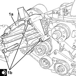
1. Place the timing side rigid engine support (1a) in its housing and secure it tightening the bolts (1b) to the recommended torque. | Fastening | Component | Ø | Value(daNm) |
|---|
| 1b | Bolt | RIGID ENGINE MOUNT, TIMING SIDE | M10 | (Engine crankcase side) 4.5 - 5.5 |
Apply silicon sealant to the entire perimeter of the crankcase sump.1. Place the sump on the crankcase.2. Tighten the front and rear bolts (2a) fixing the crankcase sump to the recommended torque using the tool (2b). | Fastening | Component | Ø | Value(daNm) |
|---|
| 2a | Front and rear bolts | OIL SUMP | M6 | (Engine crankcase side) 0.8 - 1.0 |
| Description | Code |
|---|
| 2b | Spanner | 1.860.833.001 |
3. Tighten the side bolts (3a) fixing the crankcase sump to the recommended torque using the tool (3b). | Fastening | Component | Ø | Value(daNm) |
|---|
| 3a | Side bolts | OIL SUMP | M8 | (Engine crankcase side) 2.3 - 2.8 |
| Description | Code |
|---|
| 3b | Spanner | 1.860.834.001 |
Tighten the engine oil drain plug to the recommended torque. | Fastening | Component | Ø | Value(daNm) |
|---|
| - | - | ENGINE OIL DRAIN PLUG | M18 | (Crankcase sump side) 1.8 - 2.2 |
Rotate the engine through 180° on the overhaul stand.Position the cylinder head locating bushes on the engine block.Fit a new cylinder head gasket in position.Position cylinder no. 1 at T.D.C.Position the cylinder head on the crankcase, ensuring that the cylinder 1 valves are closed. | Do not reuse the cylinder head bolts more than four times because they undergo permanent lengthening whenever they are tightened.Replace the bolts if the number of times that the bolts have been tightenened to the cylinder head is unknown. |
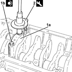
1. Tighten the cylinder head bolts (1a) to the recommended torque using the angular tightening tool (1b). | Follow the order shown in the figure for each tightening sequence. |
| Use commercial wrench USAG 233 1/2 S to loosen/tighten the cylinder head bolts. |
| Fastening | Component | Ø | Value(daNm) |
|---|
| 1a | Bolt | CYLINDER HEAD | M10 | (Engine crankcase side) 2.0 +2.0 + 90° + 90° + 90° |
| Description | Code |
|---|
| 1b | Torque wrench | 1.860.942.000 |
Connect the electrical connection to the engine oil pressure warning light switch.Connect the electrical connection to the detonation sensor.Connect the electrical connection for the engine rpm sensor.Connect the coolant supply pipe to the engine oil heat exchanger, thermostat side, and tighten the band.Connect the coolant return pipe from the engine oil heat exchanger, water pump rigid inlet pipe and tighten the band.Tighten the nut fixing the coolant supply/return pipes mounting bracket to the engine oil heat exchanger.Connect the cam angle sensor electrical connection and secure the wiring to the fastenings on the modular intake manifold.Refit the side timing belt covers and secure them using the bolts.1. Fit the tool (1a) complete with dial gauge (1b) in the seat for the spark plug for cylinder no. 1. | Description | Code |
|---|
| 1a | Extension | 1.860.895.001 |
Rotate the crankshaft in a clockwise direction until the piston for cylinder no. 1 is at T.D.C. on the ignition stroke. | If TDC is exceeded, do not turn backwards but proceed with the rotation in the same direction rotating the crankshaft through another two revolutions and return the piston for cylinder no. 1 to TDC. |
1. Undo the inlet side driven timing pulley bolt (1a) using the tool (1b) for counter-torque. | Description | Code |
|---|
| 1b | Counter-torque | 1.860.856.001 |
2. Undo the exhaust side driven timing pulley bolt (2a) using the tool (2b) for counter-torque. | Description | Code |
|---|
| 2b | Spanner for rotating timing pullies | 1.860.831.002 |
Undo the bolts and remove the inlet side camshaft fourth cap and the exhaust side camshaft second cap.1. Fit the tool (1a) in place of the camshaft caps that have been removed and secure them tightening the bolts (1b) to the recommended torque. | Check that the camshaft cam profile and the tool are correctly aligned. |
| Description | Code |
|---|
| 1a | Templates | 1.870.859.000 |
| Fastening | Component | Ø | Value(daNm) |
|---|
| 1b | Bolt | TEMPLATES FOR ENGINE TIMING | M7 | (Cylinder head side) 1.0 |
1. Fit the timing toothed drive belt in the following order:toothed drive pulley (1a)fixed tensioner (1b)exhaust side toothed driven pulley (1c) | Before fitting the belt on the exhaust side toothed driven pulley, turn clockwise (see figure) to the end of its travel. |
inlet side toothed driven pulley (1d) | Before fitting the belt on the intake side toothed driven pulley, turn clockwise (see figure) to the end of its travel. |
moving tensioner (1e)water pump pulley (1f). | The belt is fitted with the arrow facing the direction of rotation of the engine (clockwise - timing end). |
1. Use the tool to rotate the moving timing tensioner until the timing belt is completely taut. | Description | Code |
|---|
| 1 | Spanner | 1.822.149.000 |
2. Tighten the nut fixing the moving timing tensioner to the recommended torque. | Fastening | Component | Ø | Value(daNm) |
|---|
| 2 | Nut | MOBILE TIMING TENSIONER | M8 | 2.3 ÷ 2.8 |
1. Tighten the bolts (1a) for the inlet side toothed timing driven pulley using tool (1b) for counter-torque. | Fastening | Component | Ø | Value(daNm) |
|---|
| 1a | Bolt | TIMING DRIVEN PULLIES | M6 | (Inlet camshaft side) 0.8 - 1.0 |
| Description | Code |
|---|
| 1b | Counter-torque | 1.860.856.001 |
2. Tighten the exhaust side driven timing pulley bolt (2a) to the specified torque using the tool (2b) for counter-torque. | Fastening | Component | Ø | Value(daNm) |
|---|
| 2a | Bolt | TIMING DRIVEN PULLIES | M12 | (Exhaust camshaft side) 10.8 - 13.2 |
| Description | Code |
|---|
| 2b | Spanner for rotating timing pullies | 1.860.831.002 |
Remove the camshaft timing tools. | Description | Code |
|---|
| - | Templates | 1.870.859.000 |
Place the camshaft caps previously removed in their housings and secure them tightening the bolts to the recommended torque. | Fastening | Component | Ø | Value(daNm) |
|---|
| - | Bolt | CAMSHAFT SUPPORTS | M7 | (Cylinder head side) 1.4 - 1.7 |
Rotate the crankshaft through two revolutions in its direction of rotation (clockwise - timing side) and position the piston for cylinder no.1 at TDC.1. Insert tool (1a) to hold the mobile timing belt tensioner still and loosen tensioner nut (1b). | Description | Code |
|---|
| 1a | Spanner | 1.822.149.000 |
2. Turn tool (2a) anticlockwise (timing end) to align the tensioner mobile pointer (2b) with reference hole (2c). | Description | Code |
|---|
| 2a | Spanner | 1.822.149.000 |
3. Tighten the nut fixing the moving timing tensioner to the recommended torque. | Fastening | Component | Ø | Value(daNm) |
|---|
| 3 | Nut | MOBILE TIMING TENSIONER | M8 | 2.3 ÷ 2.8 |
Turn the crankshaft through two turns in the direction of rotation (clockwise - timing end) to move cylinder 1 to TDC in combustion stage and check that the engine timing is correct using the tool. | Description | Code |
|---|
| - | Templates | 1.870.859.000 |
Remove the tool for checking T.D.C. from the housing for the spark plug for cylinder no.1. | Description | Code |
|---|
| - | Extension | 1.860.895.001 |
Place the spark plug for cylinder no.1 in its housing and tighten it to the recommended torque. | Fastening | Component | Ø | Value(daNm) |
|---|
| - | - | SPARK PLUGS | M14 | (Cylinder head side) 2.4 - 3.0 |
- Position the crankshaft pulley in its housing and secure it tightening the bolts to the recommended torque. | Fastening | Component | Ø | Value(daNm) |
|---|
| - | Bolt | COUNTER-ROTATING SHAFT DRIVE PULLEY | M6 | (Timing belt drive pulley side) 0.8÷1.0 |
1. Turn the counterrotating shafts until the notches (1a) on the pulleys are aligned with the ribs (1b).2. Fit the lower protective timing cover and the crankshaft pulley provisionally and check the alignment of the notches stamped on the parts.Fit the counterrotating shaft toothed drive belt
1. Tension the counterrotating shaft toothed drivebelt using tool (1a) to move alignment hole (1b) on the tensioner to the middle of the rotation sector. | Description | Code |
|---|
| 1a | Spanner | 1.822.154.000 |
2. Tighten the nut fixing the toothed timing belt tensioner to the recommended torque. | Fastening | Component | Ø | Value(daNm) |
|---|
| 2 | Nut | BELT TENSIONER COUNTER-ROTATING SHAFT | M6 | (Left counter-rot shaft cover side) 0.8 - 1.0 |
1. Fit the lower timing belt covers (1a) and secure them using the bolts (1b).2. Position the crankshaft pulley (2a) in its housing and secure it tightening the bolts (2b) to the recommended torque. | Fastening | Component | Ø | Value(daNm) |
|---|
| 2b | Bolt | CRANKSHAFT PULLEY | M8 | 2.3 ÷ 2.8 |
1. Place the cam cover (1a), complete with gasket, back in its housing and secure it tightening the bolts (1b) to the recommended torque. | Fastening | Component | Ø | Value(daNm) |
|---|
| 1b | Bolt | CAM COVER | M6 | (Cylinder head side) 0.8 - 1.0 |
1. Replace the ignition coils (1a) in their housings with gaskets and secure them tightening the bolts (1b) to the recommended torque. | Fastening | Component | Ø | Value(daNm) |
|---|
| 1b | Bolt | IGNITION COIL/REEL | M6 | (Cam cover side) 0.8 ÷ 1.0 |
Fit the bulkhead coupling in its housing and secure it using the bolts.Connect the battery earth lead to the cam cover and secure it using the bolt.Connect the electrical connections to the ignition coils.Proceed with the refitting Op. 1004D40 ENGINE - POSITION ON STAND AND REMOVE.