125000939 - 1024A10 CRANK SHAFT - R + R WITH ENGINE REMOVED - CHECK MAIN AND CONNECTING ROD BEARINGAND REPLACE IF NECESSARY

Removing
(
Refitting
)
Proceed with the removal Op. 1004D40 ENGINE - POSITION ON STAND AND REMOVE.1. Disconnect the electrical connections from the ignition coils. | Description | Connector |
|---|
| 1 | Ignition coil | See A30 IGNITION ''COIL |
2. Undo the bolt (2a) and disconnect the earth lead (2b) from the tappet cover.3. Undo the bolts (3a) and move the cable duct (3b) to the side.
1. Undo the bolts (1a) and remove the ignition coils (1b).
1. Undo the bolts (1a) and remove the tappet cover (1b) complete with gasket.
1. Undo the bolts (1a) and remove the crankshaft pulley (1b).2. Undo the bolts (2a) and remove the lower protective timing cover (2b).
1. Loosen the counter-balance shaft toothed belt tensioner nut.2. Release and remove the counter-balance shaft toothed timing belt.
1. Loosen the nut retaining the timing belt moving tensioner.2. Release and remove the toothed timing drive belt.
1. Undo the plug and drain the engine oil. | Collect the engine oil in a suitable container. |
Rotate the engine through 180° on the overhaul stand.1. Undo the front and rear bolts (1a) fixing the crankcase sump using the tool (1b). | Description | Code |
|---|
| 1b | Spanner | 1.860.833.001 |
2. Undo the side bolts (2a) fixing the crankcase sump using the tool (2b). | Description | Code |
|---|
| 2b | Spanner | 1.860.834.001 |
3. Cut the crankcase sump sealant using the tool. | Description | Code |
|---|
| 3 | Blade | 1.870.718.000 |
4. Remove the crankcase sump.
1. Undo bolts (1a) and remove the timing side engine support (1b).2. Undo the bolts (2a) and remove the counter-balance shaft toothed belt drive pulley (2b).
1. Fit the flywheel lock. | Description | Code |
|---|
| 1 | Counter-torque | 1.860.846.001 |
1. Undo the bolt (1a) (left hand thread) and remove the toothed drive pulley (1b).
1. Undo the bolts (1a) and remove the engine flywheel (1b). | The bolts fixing the flywheel have been treated with a special agent; therefore they should be replaced each time they are removed. |
2. Remove the flywheel lock. | Description | Code |
|---|
| 2 | Counter-torque | 1.860.846.001 |
1. Undo the bolts (1a) and remove the flywheel guard (1b).
1. Unscrew the bolt securing the engine oil intake duct to the main bearing cap.
1. Undo the bolts (1a) and remove the engine block front cover (1b) with the built-in oil pump complete with intake (1c), engine oil heat exchanger (1d) and engine oil filter (1e).2. Remove the gasket.
Release the oil seal from the crankcase front cover. | Take care not to damage the oil seal seat during its removal. |
1. Fit the tool for rotating the crankshaft. | Description | Code |
|---|
| 1 | Flange | 1.820.618.000 |
Rotate the crankshaft using the tool fitted previously so that the connecting rod cap bolts are accessible.1. Undo the bolts (1a) and remove the connecting rod caps (1b) and half-bearings (1c).2. Remove the tool for rotating the crankshaft. | Description | Code |
|---|
| 2 | Flange | 1.820.618.000 |
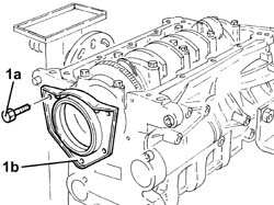
1. Undo the bolts (1a) and remove the crankcase rear cover with the oil seal (1b) incorporated.
Check that the crankshaft endfloat corresponds to the recommended figures using a magnetic base and dial gauge. | Measurement | | Value |
|---|
| - | Crankshaft endfloat (mm) | | 0.059 ÷ 0.221 |
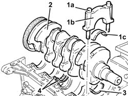
1. Undo the bolts (1a) and remove the main journal caps (1b) complete with half-bearings (1c).2. Remove the crankshaft.3. Remove the main journal half-bearings.4. Remove the thrust washers.
Refitting
(
Removing
)
Check that the half-bearings show no signs of grooves or traces of seizing; if this is not the case, they must be replaced. | No adjustment operations whatsoever should be carried out to the half-bearings. |
Check that the thickness of the half-bearings corresponds to the recommended figures; if not, replace them. | Measurement | | Value |
|---|
| - | Main bearing thickness (mm) | Category A | 1.836 ÷ 1.840 |
| Category B | 1.839 ÷ 1.843 |
| Category C | 1.842 ÷ 1.846 |
Check that the thickness of the connecting rod half-bearings is within specified limits; if not, replace them. | Measurement | | Value |
|---|
| - | Connecting rod bearing thickness (mm) | Category A | 1.527 ÷ 1.531 |
| Category B | 1.530 ÷ 1.534 |
| Category C | 1.533 ÷ 1.537 |
| The main and connecting rod half-bearings used on this engine have been selected for their optimum fitting clearance. |
| The crankshaft supplied by the Parts Dept. comes without half-bearings and the main journals and crankpins are the "normal" size; the half-bearings to be fitted must therefore be selected identifying the class of each main journal and crankpin for the new crankshaft. |
The following must be determined for the selection of main journal half-bearings:
- The numerical code stamped on the flywheel;
- the paint mark, if present, next to the main journals.
Below is an example of the identification of main journal grades.
1 - Crankpin identification numerical code: the left number refers to the first timing side bearing; the final "N" is an insignificant code for 4 cylinder engines.2 - Main journal identification numerical code: the first number refers to the first timing side bearing; the final "N" is an insignificant code for 4 cylinder engines.3 - Series of numbers (if present), in groups of two digits, which indicate the dimensions (thousandth part) of the main journals: the first two numbers on the left refer to the first timing side bearing. | Only use the codes that relate to the key, all other codes on the flywheel should not be used. |
For the identification of the main journal grade, refer to the numerical code for reference 2 in the key.In the case of the example, the numbers 11111N indicate that all five bearings are Grade A (red) as indicated below.A further method for identifying the grade of the bearings is to read reference 3 (if present) in the diagram.In the case of the example, the number 84 (first on the left) corresponds to the dimensions 52.984 for the first timing side bearing which identifies Grade A (red); the same method should be applied for other groups of two digits for the same reference 3 (87 -85 -85 -84).MAIN JOURNAL IDENTIFICATIONMain journal grade A (normal), diameter 52.982.52.988 mm, RED paint mark, numerical code 1 (82 88)*Main journal grade B (normal), diameter 52.982.52.994 mm, BLUE paint mark, numerical code 2 (88 94)*Main journal grade C (normal), diameter 52.994.53.000 mm, YELLOW paint mark, numerical code 3 (94 00)*Main journal grade D (0.127 mm undersize), diameter 52.885.52.861 mm, BROWN paint mark, numerical code 6 (55 61)*Main journal grade E (0.127 mm undersize), diameter 52.861.52.867 mm, GREEN paint mark, numerical code 7 (61 67)*Main journal grade F (0.127 mm undersize), diameter 52.867.52.873 mm, BLACK paint mark, numerical code 8 (67 73)*(*): Last two numbers (thousandth part) of the main journal dimensions.- In the case of the usage of a crankshaft where the maximum undersize for the bearings is 0.127 mm through grindings, the grade should be selected through the measurement of the diameter of the bearing using the above as a reference.- Having defined the grade and the colour of each new or reground crankshaft bearings, it is necessary to select the thickness of the half-bearings that should be the same colour as the corresponding bearing; the pair of half-bearings required can be ordered from the Parts Dept. by quoting the order no.The above is designed to guarantee the optimum operational clearances for all the bearings.Lastly, we wish to point out that,in general, the clearance between the main journal and the half-bearing, produced through the selection method described above, should be 0.031 - 0.051 mm; this figure can be measured, as part of the final check, using the calibrated wire (Plastic Gauge) following the instructions described below.Place the half-bearings back in their housings in the engine block as described previously. | Great care should be taken over cleanliness when refitting. |
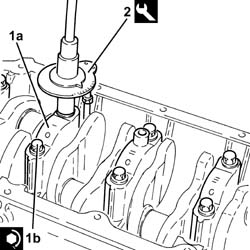
1. Place the crankshaft in its housing.2. Fit the calibrated wire (plastigage) for measuring the bearing clearance.
1. Place the bearing cap (1a), complete with half-bearing, back in its housing and secure it tightening the bolts (1b) to the recommended torque. | The bearing caps are marked with progressively numbered references (from zero to four starting from the front of the engine) which define the fitting position. |
| The safety references on the cylinder block/crankcase and on the bearing caps should be on the same side. |
| Fastening | Component | Ø | Value(daNm) |
|---|
| 1b | Nut | MAIN BEARING CAPS | M12 | (Engine crankcase side) 2.5 + 79° |
2. Use the tool for the angular tightening of the bearing cap bolts. | Description | Code |
|---|
| 2 | Torque wrench | 1.860.942.000 |
1. Remove the bearing cap fitted previously and, using a suitable graduated measuring instrument (1a), measure the clearance shown by the calibrated wire (1b). | Measure the clearance for all the bearings taking care to take the measurements one at a time without moving the crankshaft at any time. |
| Measurement | | Value |
|---|
| 1 | Main journal/half-bearing clearance (mm) | | 0.031 ÷ 0.051 |
| If the figure measured is outside of the tolerance, replace the half-bearings with ones of the correct size and category. |
Place the half-bearings in their seats.Place the thrust washers (with the size depending on the crankshaft endfloat measured during the dismantling) in their housings in the third bearing support. | The thrust washer lubrication ducts should be facing the crankshaft thrust washers. |
Place the crankshaft in its housing.1. Place the bearing caps (1a), complete with half-bearing, back in their housings and secure them tightening the bolts (1b) to the recommended torque. | The bearing caps are marked with progressively numbered references (from zero to four starting from the front of the engine) which define the fitting position. |
| The safety references on the cylinder block/crankcase and on the bearing caps should be on the same side. |
| Fastening | Component | Ø | Value(daNm) |
|---|
| 1b | Bolt | MAIN BEARING CAPS | M12 | 2.4 ÷ 2.6 + 100? |
2. Use the tool for the angular tightening of the bearing cap bolts. | Description | Code |
|---|
| 2 | Torque wrench | 1.860.942.000 |
1. Fit the tool for rotating the crankshaft. | Description | Code |
|---|
| 1 | Flange | 1.820.618.000 |
| The main and connecting rod half-bearings used on this engine have been selected for their optimum fitting clearance. |
| The crankshaft supplied by the Parts Dept. comes without half-bearings and the main journals and crankpins are the "normal" size; the half-bearings to be fitted must therefore be selected identifying the class of each main journal and crankpin for the new crankshaft. |
The following must be determined for the selection of crank pin half-bearings:
- The numerical code stamped on the flywheel;
- the paint mark, if present, next to the crank pins.
Below is an example of the identification of crank pin grades.
1 - Crankpin identification numerical code: the left number refers to the first timing side bearing; the final "N" is an insignificant code for 4 cylinder engines.2 - Main journal identification numerical code: the first number refers to the first timing side bearing; the final "N" is an insignificant code for 4 cylinder engines.3 - Series of numbers (if present), in groups of two digits, which indicate the dimensions (thousandth part) of the main journals: the first two numbers on the left refer to the first timing side bearing. | Only use the codes that relate to the key, all other codes on the flywheel should not be used. |
For the identification of the crank pin grade, refer to the numerical code for reference 1 in the key.In the case of the example, the numbers 2222N indicate that all four bearings are Grade B (blue) as indicated below.CRANK PIN IDENTIFICATIONCrank pin grade A (normal), diameter 50.787.50.793 mm, RED paint mark, numerical code 1 (87 93)*Crank pin grade B (normal), diameter 50.793.50.799 mm, BLUE paint mark, numerical code 2 (93 99)*Crank pin grade C (normal), diameter 50.799.50.805 mm, YELLOW paint mark, numerical code 3 (99 05)*Crank pin grade D (0.127 mm undersize), diameter 50.660.50.666 mm, BROWN paint mark, numerical code 6 (60 66)*Main journal grade E (0.127 mm undersize), diameter 50.666.50.672 mm, GREEN paint mark, numerical code 7 (66 72)*Crank pin grade F (0.127 mm undersize), diameter 50.672.50.678 mm, BLACK paint mark, numerical code 8 (72 78)*(*): Last two numbers (thousandth part) of the main journal dimensions.- In the case of the usage of a crankshaft where the maximum undersize for the bearings is 0.127 mm through grindings, the grade should be selected through the measurement of the diameter of the bearing using the above as a reference.- Having defined the grade and the colour of each new or reground crankshaft bearings, it is necessary to select the thickness of the half-bearings that should be the same colour as the corresponding bearing; the pair of half-bearings required can be ordered from the Parts Dept. by quoting the order no.The above is designed to guarantee the optimum operational clearances for all the bearings.Lastly, we wish to point out that, in general, the clearance between the crank pin and the half-bearing, produced through the selection method described above, should be 0.030 - 0.056 mm; this figure can be measured, as part of the final check, using the calibrated wire (Plastic Gauge) following the instructions described below.Rotate the crankshaft so that the connecting rod pins are accessible.1. Fit the calibrated wire (plastigage) for measuring the bearing clearance.
1. Place the bearing cap (1a), complete with half-bearing, selected as described previously, back in its housing and secure it tightening the bolts (1b) to the recommended torque. | The references on the connecting rod cap and the big end should be on the same side. |
| Fastening | Component | Ø | Value(daNm) |
|---|
| 1b | Bolt | CONNECTING ROD CAPS | M9 | 2.4 ÷ 2.6 +60? |
2. Use the tool for the angular tightening of the connecting rod cap bolts. | Description | Code |
|---|
| 2 | Torque wrench | 1.860.942.000 |
1. Remove the crank pin cap fitted previously and, using a suitable graduated measuring instrument (1a), measure the clearance shown by the calibrated wire (1b). | Carry out the operation of measuring the clearance for all the bearings, taking care to do it, one at a time. |
| Measurement | | Value |
|---|
| - | Crank pin/half-bearing clearance (mm) | | 0.030 ÷ 0.056 |
| If the figure measured is outside of the tolerance, replace the half-bearings with ones of the correct size and category. |
1. Place the crank pin caps (1a), complete with half-bearing, back in their housings and secure them tightening the bolts (1b) to the recommended torque. | The references on the connecting rod cap and the big end should be on the same side. |
| Fastening | Component | Ø | Value(daNm) |
|---|
| 1b | Bolt | CONNECTING ROD CAPS | M9 | 2.4 ÷ 2.6 +60? |
2. Use the tool for the angular tightening of the connecting rod cap bolts. | Description | Code |
|---|
| 2 | Torque wrench | 1.860.942.000 |
Remove the tool for rotating the crankshaft. | Description | Code |
|---|
| - | Flange | 1.820.618.000 |
1. Fit the crankcase rear cover (1a) with the oil seal incorporated using a suitable tool (1b). | Description | Code |
|---|
| 1b | Fitting tool | 1.820.619.000 |
2. Tighten the bolts fixing the crankcase rear cover with built-in oil seal to the recommended torque. | Fastening | Component | Ø | Value(daNm) |
|---|
| 2 | Bolt | CRANKSHAFT REAR COVER | M6 | (Engine crankcase side) 0.8 - 1.0 |
1. Fit the oil seal (1a) on the crankcase front cover using the tool (1b). | Description | Code |
|---|
| 1b | Fitting tool | 1.821.147.000 |
Rotate the engine through 180° on the overhaul stand.1. Place the crankcase front cover (1a) with the engine oil pump incorporated, complete with gasket (1b), intake (1c) and engine oil heat exchanger (1d) in its housing.2. Tighten the bolts securing the crankcase front cover to the recommended torque. | Fastening | Component | Ø | Value(daNm) |
|---|
| 2 | Bolt | FRONT COVER CRANKSHAFT | M6 | (Engine crankcase side) 0.8 - 1.0 |
Unscrew the bolt securing the engine oil intake duct to the main bearing cap.Place the flywheel guard in its housing and secure it using the bolts.1. Fit the flywheel lock. | Description | Code |
|---|
| 1 | Counter-torque | 1.860.846.000 |
2. Place the flywheel (2a) in its housing and secure it by tightening the new bolts (2b) which have been pretreated with sealant to the recommended torque. | The bolts fixing the flywheel have been treated with a special agent; therefore they should be replaced each time they are removed. |
| Fastening | Component | Ø | Value(daNm) |
|---|
| 2b | Bolt | FLYWHEEL (MECH.) | M12 | (Crankshaft side) 14.4 - 17.6 |
Use the tool for the angular tightening of the flywheel fixing bolts. | Description | Code |
|---|
| - | Torque wrench | 1.860.942.000 |
1. Position the toothed timing drive pulley (1a) in its housing and secure it tightening the (left hand thread) bolt (1b) to the recommended torque. | Fastening | Component | Ø | Value(daNm) |
|---|
| 1b | Left hand bolt | DRIVE PULLEY(PULLIES) TIMING | M16 | (Crankshaft side) 20.9 - 23.1 |
Remove the flywheel lock. | Description | Code |
|---|
| - | Counter-torque | 1.860.846.001 |
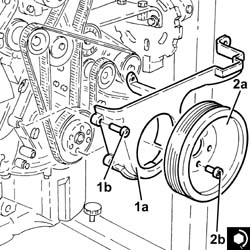
1. Place the timing side rigid engine support (1a) in its housing and secure it tightening the bolts (1b) to the recommended torque. | Fastening | Component | Ø | Value(daNm) |
|---|
| 1b | Bolt | RIGID ENGINE MOUNT, TIMING SIDE | M10 | (Engine crankcase side) 4.5 - 5.5 |
Apply silicon sealant to the entire perimeter of the crankcase sump.1. Place the sump on the crankcase.2. Tighten the front and rear bolts (2a) fixing the crankcase sump to the recommended torque using the tool (2b). | Fastening | Component | Ø | Value(daNm) |
|---|
| 2a | Front and rear bolts | OIL SUMP | M6 | (Engine crankcase side) 0.8 - 1.0 |
| Description | Code |
|---|
| 2b | Spanner | 1.860.833.001 |
3. Tighten the side bolts (3a) fixing the crankcase sump to the recommended torque using the tool (3b). | Fastening | Component | Ø | Value(daNm) |
|---|
| 3a | Side bolts | OIL SUMP | M8 | (Engine crankcase side) 2.3 - 2.8 |
| Description | Code |
|---|
| 3b | Spanner | 1.860.834.001 |
Tighten the engine oil drain plug to the recommended torque. | Fastening | Component | Ø | Value(daNm) |
|---|
| - | - | ENGINE OIL DRAIN PLUG | M18 | (Crankcase sump side) 1.8 - 2.2 |
Rotate the engine through 180° on the overhaul stand.1. Fit the tool (1a) complete with dial gauge (1b) in the seat for the spark plug for cylinder no. 1. | Description | Code |
|---|
| 1a | Extension | 1.860.895.001 |
Rotate the crankshaft in a clockwise direction until the piston for cylinder no. 1 is at T.D.C. on the ignition stroke. | If TDC is exceeded, do not turn backwards but proceed with the rotation in the same direction rotating the crankshaft through another two revolutions and return the piston for cylinder no. 1 to TDC. |
1. Undo the inlet side driven timing pulley bolt (1a) using the tool (1b) for counter-torque. | Description | Code |
|---|
| 1b | Counter-torque | 1.860.856.001 |
2. Loosen the exhaust side driven timing pulley bolt (2a) using the tool (2b) for counter-torque. | Description | Code |
|---|
| 2b | Spanner for rotating timing pullies | 1.860.831.002 |
Undo the bolts and remove the inlet side camshaft fourth cap and the exhaust side camshaft second cap.1. Fit the tool (1a) in place of the camshaft caps that have been removed and secure them tightening the bolts (1b) to the recommended torque. | Check that the camshaft cam profile and the tool are correctly aligned. |
| Description | Code |
|---|
| 1a | Templates | 1.870.859.000 |
| Fastening | Component | Ø | Value(daNm) |
|---|
| 1b | Bolt | TEMPLATES FOR ENGINE TIMING | M7 | (Cylinder head side) 1.0 |
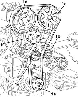
1. Fit the timing toothed drive belt in the following order as illustrated:toothed drive pulley (1a)fixed tensioner (1b)exhaust side toothed driven pulley (1c) | Before fitting the belt on the exhaust side driven toothed pulley, rotate it in a clockwise direction (see diagram) until it is in the end of travel position. |
inlet side toothed driven pulley (1d). | Before fitting the belt on the inlet side driven toothed pulley, rotate it in a clockwise direction (see diagram) until it is in the end of travel position. |
moving tensioner (1e)water pump pulley (1f). | The belt is fitted with the arrow facing the direction of rotation of the engine (clockwise - timing side). |
1. Using the tool, rotate the moving timing tensioner until the timing belt is completely taut. | Description | Code |
|---|
| 1 | Spanner | 1.822.149.000 |
2. Tighten the nut fixing the moving timing tensioner to the recommended torque. | Fastening | Component | Ø | Value(daNm) |
|---|
| 2 | Nut | MOBILE TIMING TENSIONER | M8 | 2.3 ÷ 2.8 |
1. Tighten the bolts (1a) for the inlet side toothed timing driven pulley using tool (1b) for counter-torque. | Fastening | Component | Ø | Value(daNm) |
|---|
| 1a | Bolt | TIMING DRIVEN PULLIES | M6 | (Inlet camshaft side) 0.8 - 1.0 |
| Description | Code |
|---|
| 1b | Counter-torque | 1.860.856.001 |
2. Tighten the exhaust side driven timing pulley bolt (2a) to the recommended torque using the tool (2b) for counter-torque. | Fastening | Component | Ø | Value(daNm) |
|---|
| 2a | Bolt | TIMING DRIVEN PULLIES | M12 | (Exhaust camshaft side) 10.8 - 13.2 |
| Description | Code |
|---|
| 2b | Spanner for rotating timing pullies | 1.860.831.002 |
Remove the camshaft timing tools. | Description | Code |
|---|
| - | Templates | 1.870.859.000 |
Place the camshaft caps previously removed in their housings and secure them tightening the bolts to the recommended torque. | Fastening | Component | Ø | Value(daNm) |
|---|
| - | Bolt | CAMSHAFT SUPPORTS | M7 | (Cylinder head side) 1.4 - 1.7 |
Rotate the crankshaft through two revolutions in its direction of rotation (clockwise - timing side) and position the piston for cylinder no.1 at TDC.1. Insert the tool (1a) for keeping the timing moving tensioner still and loosen the tensioner nut (1b). | Description | Code |
|---|
| 1a | Spanner | 1.822.149.000 |
2. Rotate the tool (2a) in an anti-clockwise direction (timing side) until the tensioner moving reference (2b) coincides with the reference opening (2c). | Description | Code |
|---|
| 2a | Spanner | 1.822.149.000 |
3. Tighten the nut fixing the moving timing tensioner to the recommended torque. | Fastening | Component | Ø | Value(daNm) |
|---|
| 3 | Nut | MOBILE TIMING TENSIONER | M8 | 2.3 ÷ 2.8 |
Rotate the crankshaft through two revolutions in its direction of rotation (clockwise - timing side) until cylinder no.1 is at TDC in the explosion stroke and check that the engine timing is correct using the tool. | Description | Code |
|---|
| - | Templates | 1.870.859.000 |
Remove the tool for checking T.D.C. from the housing for the spark plug for cylinder no.1. | Description | Code |
|---|
| - | Extension | 1.860.895.001 |
Place the spark plug for cylinder no.1 in its housing and tighten it to the recommended torque. | Fastening | Component | Ø | Value(daNm) |
|---|
| - | - | SPARK PLUGS | M14 | (Cylinder head side) 2.4 - 3.0 |
Position the counter-balance shaft belt drive pulley in its housing and secure it tightening the bolts to the recommended torque. | Fastening | Component | Ø | Value(daNm) |
|---|
| - | Bolt | COUNTER-ROTATING SHAFT DRIVE PULLEY | M6 | (Timing drive pulley side) 0.8÷1.0 |
1. Rotate the counter-balance shafts so that the references (1a) on the pullies are in line with the ribs (1b).2. Temporarily fit the lower protective cover for the timing gear and the crankshaft pulley and check that the references are aligned.Fit the counter-balance shaft toothed drive belt
1. Tension the counter-balance shaft drive belt using the tool (1a) until the reference opening (1a) on the tensioner is in the centre of the rotation sector. | Description | Code |
|---|
| 1a | Spanner | 1.822.154.000 |
2. Tighten the nut fixing the counter-balance shaft belt tensioner to the recommended torque. | Fastening | Component | Ø | Value(daNm) |
|---|
| 2 | Nut | TENSIONER FOR COUNTER-BALANCE SHAFT(S) | M6 | (Left counter-balance shaft front cover side) 0.8 - 1.0 |
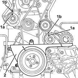
1. Fit the lower timing belt protective cover (1a) and secure it using the bolts (1b).2. Position the crankshaft pulley (2a) in its housing and secure it tightening the bolts (2b) to the recommended torque. | Fastening | Component | Ø | Value(daNm) |
|---|
| 2b | Bolt | CRANKSHAFT PULLEY | M8 | 2.3 ÷ 2.8 |
1. Place the tappet cover (1a), complete with gasket, back in its housing and secure it tightening the bolts (1b) to the recommended torque. | Fastening | Component | Ø | Value(daNm) |
|---|
| 1b | Bolt | CAM COVER | M6 | (Cylinder head side) 0.8 - 1.0 |
1. Place the ignition coils (1a) in their housings and secure them tightening the bolts (1b) to the recommended torque. | Fastening | Component | Ø | Value(daNm) |
|---|
| 1b | Bolt | IGNITION COIL/REEL | M6 | (Cam cover side) 0.8 ÷ 1.0 |
Fit the cable duct in its housing and secure it using the bolts.Connect the earth lead to the tappet cover and secure it using the bolt.Connect the electrical connections to the ignition coils.Proceed with the refitting Op. 1004D40 ENGINE - POSITION ON STAND AND REMOVE.