125001285 - 2127C40 HYDRAULIC SPEED SELECTION HYDRAULIC ACTUATOR UNIT AND CLUTCH - R R (Smart gearbox)
- Position the vehicle on a lift.
- Place the gear lever in neutral.
- Connect the Examiner diagnostic equipment.
- Select "Alfa Selespeed" on the Examiner.
- Select "Control Units Test" on the Examiner and select "Selespeed Marelli automatic transmission" as the system.
- Press "Active diagnosis" on the Examiner and select "Accumulator depressurization".
- Follow the procedure described on the Examiner.
- Op. 5530B10 BATTERY - R+R
- Op. 5530B52 BATTERY DRIP TRAY/SUPPORT - R.R.
- Op. 4450B02 LEFT FRONT WHEEL R R
- Op. 7055B90 LEFT FRONT WHEEL ARCH LINER - R.R.
- Undo the electro-hydraulic selection gearbox hydraulic circuit fluid reservoir and drain the reservoir using a syringe.
| Do not reuse the fluid from the gear selection electro-hydraulic system circuit. |
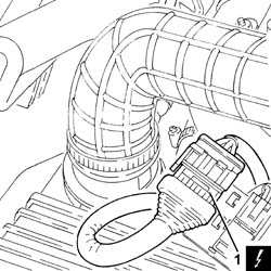
- Disconnect the electrical connection for the hydraulic gear activation unit wiring.
| Description | Connector | |
|---|---|---|
| 1 | Gearbox sensor coupling | See D79 TRANSMISSION SENSOR JUNCTION |
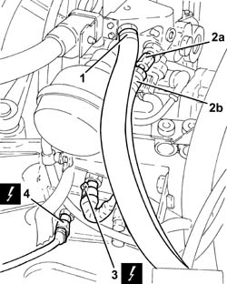
| Collect the fluid from the circuit that comes out and should not be reused. |
| Description | Connector | |
|---|---|---|
| 3 | Gearbox output speed sensor | See K77 TRANSMISSION OUTPUT SPEED SENSOR |
| Description | Connector | |
|---|---|---|
| 4 | Reversing lights switch | See I20 REVERSING LIGHTS SWITCH |
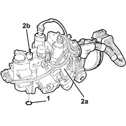
- Release the clutch push rod cover.
- Undo the locknut (2a) and fully tighten the clutch push rod (2b).
- Retract the clutch push rod and insert the tool.
| Description | Code | |
|---|---|---|
| 3 | Pin | 1.870.753.002 |
| The tool should be fully tightened and should not be removed in order to allow the hydraulic unit to be correctly fitted. |
| Description | Code | |
|---|---|---|
| 1b | Pin | 1.870.753.001 |
- Op. 7055B54 UNDER-ENGINE GUARD - R R
- Position a hydraulic jack beneath the gearbox.
- Loosen the bolt securing the gearbox side power unit rigid support to the flexible mounting as necessary.
- Remove the hydraulic jack.
| This operation is necessary to unscrew the bolt fixing the hydraulic actuator unit to the gearbox control shaft. |
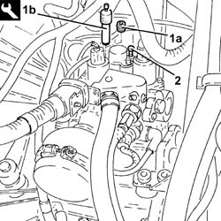
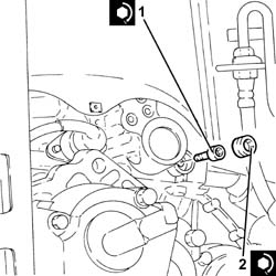
- Loosen the cap.
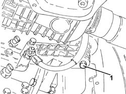
- Undo the bolt (M8 x 16) fixing the hydraulic actuator unit to the gearbox control shaft.
| The above bolt is the pre-treated type and it therefore cannot be reused when refitting. |
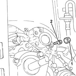
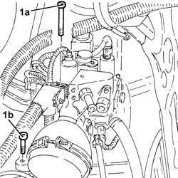
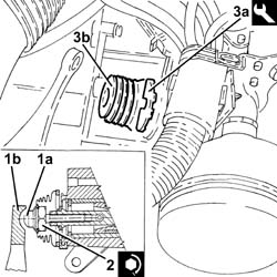
- Undo the remaining bolts (1a) (M6 x 110) and (1b) (M8 x 30) fixing the electro-hydraulic gear selection hydraulic implementation unit and clutch.
| These bolts are the pre-treated type and therefore cannot be reused when refitting. |

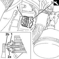
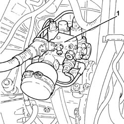
- Remove the electro-hydraulic gear and clutch selection hydraulic actuator unit and the seal.
| All the procedures described below and, in particular, the fitting sequence for the hydraulic unit and the fastening of the gearbox control shaft bolt to the hydraulic actuator unit could adversely affect the correct operation of the system if they are not carried out properly. |
| Before fitting the hydraulic actuator unit on the gearbox, clean any impurities from the thread of the gearbox shaft and/or in the hydraulic actuator housing (by blowing). |
| Clean the threaded seat for the bolt fixing the gearbox control shaft to the hydraulic actuator unit making sure that there are shavings, grease, oil, lubricants, etc. whatsoever to ensure that the threaded seat is "dry" (this condition is vital to guarantee the non-slip effect of the bolt). |
- Check manually that the gearbox shaft slides freely in its housing and that there is grease at the end of the actual shaft; if necessary, renew it.
- FITTING A NEW HYDRAULIC UNIT
| Make sure that the hydraulic actuator unit is in contact with the gearbox. |
| This operation should only be carried out after the hydraulic actuator unit has been fitted on the gearbox. |
| Description | Code | |
|---|---|---|
| 4 | Pin | 1.870.753.001 |
- FITTING THE HYDRAULIC UNIT REMOVED
- Fit the seal checking that it is intact; if the same hydraulic unit is being refitted on a new gearbox, use the seal that was removed and not the one on the new gearbox.
- Place the hydraulic actuator unit (2a) in position already complete with the tool (2b).
| Make sure that the hydraulic actuator unit is in contact with the gearbox. |
- Proceed as described below for both the fitting of a new hydraulic unit and for refitting the same hydraulic unit as was removed.
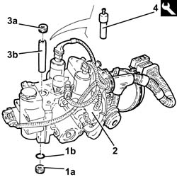
- Fit the new bolts (1a) (M6 x 110) and (1b) (M8 x 30) and tighten fully by hand.
| Always use a new bolt checking that the special treatment is present on the thread. |
| The bolt should be tightened in a single operation. |
| Fastening | Component | Ø | Value (daNm) | |
|---|---|---|---|---|
| 1 | Bolt | HYDRAULIC ACTUATOR UNIT | M8 | (Gearbox control shaft side) 2.7 - 3.3, daNm |
| Fastening | Component | Ø | Value (daNm) | |
|---|---|---|---|---|
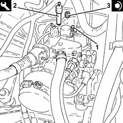
| 2 | Plug | CAP FOR BOLT SECURING GEARBOX CONTROL SHAFT TO HYDRAULIC ACTUATOR UNIT | (Hydraulic actuator unit side) 1.3 - 1.7, daNm |
| Description | Code | |
|---|---|---|
| 2 | Pin | 1.870.753.001 |
| Fastening | Component | Ø | Value (daNm) | |
|---|---|---|---|---|
| 3 | Plug | CAP FOR TOOL LOCKING HYDRAULIC UNIT SELECTION LINKAGE | (Hydraulic actuator unit side) 5.0 - 6.0, daNm |
| Do not refit the spacer used for the transportation of the new hydraulic unit because it would impede its operation. |
- Tighten the bolts tightened previously (M6 x 110) and (M8 x 30) to the recommended torque.
| Fastening | Component | Ø | Value (daNm) | |
|---|---|---|---|---|
| - | Bolt | HYDRAULIC ACTUATOR UNIT | M6 | (Gearbox side) 1.3 - 1.7, daNm |
| Fastening | Component | Ø | Value (daNm) | |
|---|---|---|---|---|
| - | Bolt | HYDRAULIC ACTUATOR UNIT | M8 | (Gearbox side) 1.3 - 1.7, daNm |
- Apply Tutela MRM2 grease to the clutch lever in the push rod housing.
| Fastening | Component | Ø | Value (daNm) | |
|---|---|---|---|---|
| 2 | Nut | CLUTCH CONTROL PUSH ROD LOCKNUT | 0.5 - 0.7, daNm |
| Description | Code | |
|---|---|---|
| 3a | Pin | 1.870.753.002 |
- Tighten the bolt securing the power unit gearbox side rigid support to the flexible mounting to the recommended torque.
| Fastening | Component | Ø | Value (daNm) | |
|---|---|---|---|---|
| - | Bolt | GEARBOX SIDE RIGID SUPPORT FOR POWER UNIT | M10 | 4.0 - 5.0, daNm |
| Take care to prevent any impurities from entering the hydraulic circuit. |
| Fastening | Component | Ø | Value (daNm) | |
|---|---|---|---|---|
| 3b | Connector | PIPE FROM PUMP/ACTUATOR UNIT | (Actuator unit side) 1.8 - 2.2, daNm |
| Take care to prevent any impurities from entering the hydraulic circuit. |
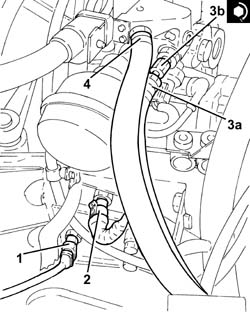
- Connect the electrical connection for the hydraulic gear activation unit wiring.
- Op. 0010T47 HYDRAULIC SYSTEM FLUID FOR GEARBOX WITH HYDRAULIC SELECTION CHECK LEVEL AND TOP UP IF NECESSARY
- Op. 0010T48 HYDRAULIC SYSTEM FOR GEARBOX WITH HYDRAULIC SELECTION BLEED AIR
| This operation is carried out with the bleed screw open which should be closed when the operation is completed. |
- Op. 7055B54 UNDER-ENGINE GUARD - R R
- Op. 7055B90 LEFT FRONT WHEEL ARCH LINER - R.R.
- Op. 4450B02 LEFT FRONT WHEEL R R
- Op. 5530B52 BATTERY DRIP TRAY/SUPPORT - R.R.
- Op. 5530B10 BATTERY - R+R
- Connect the Examiner diagnostic equipment.
- Select "Alfa Selespeed" on the Examiner.
- Select "Control Unit Test" on the Examiner and select "Selespeed Marelli automatic transmission" as the system.
- Press "Active diagnosis" on the Examiner and select "End of line/service autocalibration".
- Follow the procedure described on the Examiner.