3308467 - 1056B multi-point injection system (mpi) (Automatic transmission)
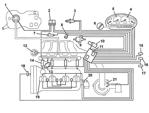
VIEW OF ASSEMBLY
-
GENERAL CHARACTERISTICS
Operation of the fuel injection-ignition
The Bosch Motronic M1.5.5 system belongs to the category of integrated systems:
- inductive discharge digital electronic ignition
- distributorless
- sequential phased electronic fuel injection (1 - 3 - 4 - 2).
During idling, the control unit checks:
- the moment of ignition
- the air flow
The system's functions are basically as follows:
- system self-adaptation
- self-test
- Recognition of the Alfa Romeo CODE
- check on cold starting
- check on combustion - Lambda probe
- check on phase transformer and modular inlet manifold
- control of detonation
- check on enrichment during acceleration
- fuel cut-off during overrunning
- fuel vapour recovery
- limitation of maximum rpm
- check on fuel-electric fuel pump supply
- connection to the climate control system
- recognition of cylinder position
- adjustment of fuel injection times
- adjustment of ignition advance values
- check and management of idle speed
- check on electric cooling fan
Fuel injection system
The essential conditions that must always be met in the preparation of the air-fuel mixture for the correct operation of controlled-ignition engines are mainly:
- the "metering" (air/fuel ratio) must constantly be kept as close as possible to the stoichiometric ratio, so as to ensure the necessary rapidity of combustion, avoiding unnecessary fuel consumption
- the "homogeneity" of the mixture, consisting of petrol vapours, diffused as finely and evenly as possible in the air.
The information processed by the control unit for controlling optimum metering is received in the form of electrical signals emitted by the:
- air flow meter and air temperature sensor, for the exact quantity of air drawn in
- rpm sensor, which generates an alternating single-phase signal whose frequency indicates the engine rpm
- butterfly casing integrated with M.D.S. to recognize the minimum, partial and full load conditions
- Lambda sensor for determining the oxygen content in the exhaust gases.
Ignition system
The ignition is of the inductive discharge type, static advance type (i.e. without a high tension distributor) with power modules located in the fuel injection control unit.The ignition system takes advantage of the "lost spark" logic: each coil supplies the spark plug for the cylinder underneath and, simultaneously, the one for the matching cylinder in the same position (centre with centre, side with side).The advantages of this solution are:
- less electrical overload;
- guaranteed constant discharge on each plug.
The control unit corrects the advance values mainly in accordance with the:
- engine coolant temperature
- intake air temperature
- knock
- throttle valve position
The information which the control unit processes to operate the ignition coils is received by means of electrical signals emitted by the:
- air flow meter and air temperature sensor, for the exact quantity of air drawn in
- rpm sensor, which generates an alternating single-phase signal whose frequency indicates the engine rpm
- knock sensor (on the rear of the engine block between the 2nd and 3rd cylinders) which recognizes which cylinder is knocking and corrects its ignition advance
- butterfly position potentiometer (integrated in the butterfly casing integrated with M.D.S.) to recognize minimum, partial and full load conditions
- timing sensor.
OPERATION
Diagram of input/output information to/from the control unit
-
OPERATING LOGICS
Self-learning
The control unit implements the self-learning logic in the following conditions:
- removing-refitting or replacement of the injection control unit
- removing-refitting or replacement of the butterfly casing integrated with M.D.S.
- removing-refitting or replacement of the air chamber.

System self-adaptation
The control unit has a self-adaptation function which recognizes changes in the engine which occur as a result of bedding-in and ageing processes of both components and the engine itself.These changes are stored in the form of modifications to the basic mapping, and their purpose is to adapt the operation of the system to the gradual alterations in the engine and components compared with their characteristics when new.This self-adaptation function also makes it possible to even out inevitable differences (due to production tolerances) in any replaced components.From the exhaust gas analysis, the control unit changes the basic mapping in relation to the original characteristics of the new engineThe self-adaptation parameters are not cancelled if the battery is disconnected.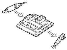
Autodiagnosis
The control unit's self-test checks the signals coming from the sensors, comparing them with the permitted limits:
- indication of starting faults
- warning light on for 4 secs indicates test stage
- warning light off after 4 secs indicates no faults in components that could affect the values established in emission control regulations
- warning light on after 4 secs indicates fault
- fault indication during operation
- warning light on indicates fault
- warning light off indicates no faults in components that could affect the values established in emission control regulations
- recovery
- the control unit defines as and when required the type of recovery depending on the faulty components
- the recovery parameters are managed by non-faulty components.

Recognition of the alfa romeo code
When the control unit receives the ignition "ON" signal, it dialogues with the Alfa Romeo CODE control unit to obtain starting enablement.Communication takes place via the dedicated bidirectional serial diagnostic line which connects the two control units.
Check on cold starting
The following occurs during cold starting:
- natural weakening of the mixture because of poor turbulence of the fuel particles at low temperatures
- lower evaporation of the fuel
- condensation of the fuel on the inner walls of the inlet manifold
- higher viscosity of the lubricating oil.
The electronic control unit recognizes this condition and corrects the fuel injection times in accordance with:
- coolant temperature
- intake air temperature
- battery voltage
- engine rpm

Check on combustion - lambda sensor
According to the engine speed and load, the control unit processes the Lambda sensor signal using a special integrator and corrects the injector opening times.
Check on timing variator and modular inlet manifold
To optimize the quantity of air drawn in by the engine, the control unit checks:
- inlet timing on two angle positions
- geometry of inelt ducts on two lengths.
At the maximum torque speed, the control unit sets the "open" phase:
- cam advanced by 25° engine
- inlet box long ducts
At the maximum power speed, the control unit sets the "closed" phase:
- cam in normal position
- inlet box short ducts.
A idle speed, the control unit sets the "closed" phase:
- cam in normal position
- inlet box long ducts

Control of detonation
The control unit detects the presence of knocking by processing the signal coming from the relevant sensor.The control unit continuously compares the signals coming from the sensor with a threshold value, which, in turn, is continuously updated to take account of background noise and ageing of the engine.The control unit is therefore capable of detecting the presence of detonation (or the onset of detonation) in each individual cylinder and reduces the ignition advance for the cylinder concerned (in steps of 3° up to a maximum of 6°) until the phenomenon disappears. The advance is then gradually restored to the basic value (in steps of 0.8°).Under acceleration conditions, a higher threshold is used to take account of the increased engine noise under such conditions.The detonation check logic also has a self-adaptation function, which memorizes the reductions in advance that may be repeated continuously, so as to adjust the mapping to the different conditions now affecting the engine.
Check on enrichment during acceleration
If during the acceleration demand, the variation in the air flow meter signal exceeds a predefined increment, the control unit increases the fuel injection time so that the required rpm is reached rapidly.When the established rpm is nearly reached, the increase in fuel injection is gradually eliminated.Recovery:
- the control unit replaces the signal coming from the faulty air flow meter with the signal from the throttle valve potentiometer.

Fuel cut-off during overrunning
During release of the accelerator pedal, and beyond a pre-established threshold, the control unit:
- cuts off the supply to the fuel injectors
- reactivates the supply to the fuel injectors at 1300-1500 rpm.
The thresholds for reactivation of the fuel supply and for fuel cut-off vary depending on:
- coolant temperatur
| ... DATA ERROR - CROPPED TEXT | Ошибка данных - Текст обрезан ... |
|---|