3308546 - 5540B headlamps
XENON HEADLAMPS
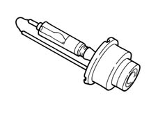
This type of lighting used for the dipped headlamps involves a bulb containing xenon gas.These headlamps have the following features:
- more effective lighting
- increased range and regulation of the luminous beam
- lower consumption at operating temperature
- longer lasting bulb.
This system is controlled by its own electronic control unit which operates on two levels:
- statically, carrying out the realignment according to the vehicle load.
- dynamically, maintaining the alignment to compensate for vehicle pitching.
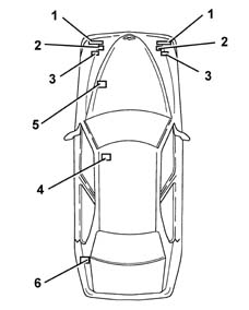
Location of components
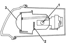
Light cluster
The light cluster has a power luminous beam at its disposal which, in order to be used to best effect, requires:
- a reflective surface (1) which collects the luminous beam
- a screen (2) which determines the shape of the luminous beam
- a spherical lens (3) which determines the depth of the luminous beam on the road.
Each headlamp is equipped with a control unit which has the following functions:
- checking the value of the operating voltage/current
- striking the arc at the electrodes and causing the salts to evaporate during ignition.
The operation of the xenon headlamps can be divided into three stages:
- Ignition, the control unit produces a high voltage (up to 20000V alternating current) capable of producing an arc (electrical discharge) between the bulb electrodes.
- Maintaining the arc, the control unit supplies the bulb with an excess current for several seconds which causes the rapid evaporation of the metallic halides contained in the bulb.
| during this stage and for less than a second, the intensity of the luminous beam is greater than during normal operation. |
| Make sure that the ignition is in the OFF position, then disconnect the negative (-) battery terminal before carrying out any operation on the light clusters. |
AUTOMATIC DYNAMIC HEADLAMP ALIGNMENT
As a result of the high light intensity, the adoption of xenon headlamps requires an automatic, dynamic system to check the headlamp alignment.This system is managed by an electronic control unit which operates the stepping actuators fitted on each dipped headlamp. The actuators are operated by processing the signals coming from the two alignment sensors.The advantages of using an automatic, dynamic headlamp alignment control system are:
- it avoids glare from oncoming vehicles
- it stabilizes the area illuminated for improved active safety.
Location of components
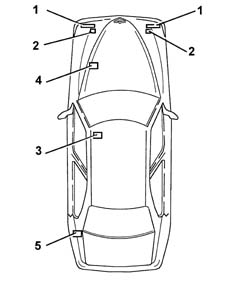
Headlamp alignment correction control unit
This is located under the driver's seat, in a horizontal position and "slide" on the support fixed to the bodyshell.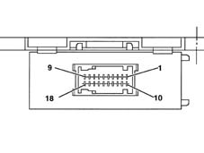
DESCRIPTION
The control unit compares the signals coming from the alignment sensors and calculates the vehicle geometry.A "correction" signal is sent to the stepping motor actuators to adjust the alignment of the luminous beam to the vehicle geometry calculated.To avoid oscillations of the dipped headlamp beam in the following cases:
- particular types of roads (cobblestones, unmade, etc.)
- sharp movements of the vehicle caused by the driver (clutch release, gear change, etc.)
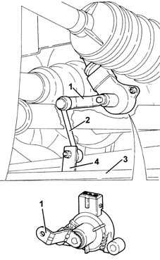
Headlamp alignment sensors
They are the resistive type and one is fitted on the front suspension on the left hand side and the other on the rear suspension on the left hand side.The actuators are supplied by the control unit (5 V) and provide a linear output signal proportional to the position of the suspension.The connection between the sensor rotation axie and the rear suspension is made by means of a "connecting rod - crank" system hinged on a self-lubricating ball joint.The crank (1) is an integral part of the actuator and is fixed to the rotation axis.The connecting rod (2) is fixed to the suspension lower track control arm (3) by a bracket.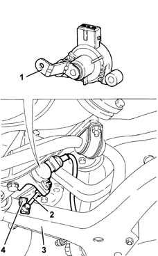
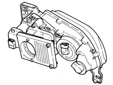
Stepping actuators
They are fitted directly on the headlamps and consist of:
- an electric stepping motor
- a screw-female screw reduction gear which transforms the rotary motion of a hinged push rod into a linear motion by means of a ball joint on the parabola.