3308554 - 5580C air bag system
DESCRIPTION
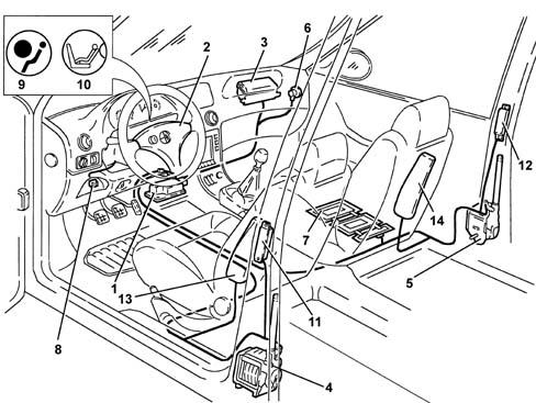
The vehicle is fitted with an Air Bag system and seat belts with electronically controlled pre-tensioners which may have:
- "4 charges" (fitted as standard)
- "6 charges" (optional).
A sensor in the seat automatically deactivates:
- the front passenger Air Bag
- the passenger pre-tensioner
- the passenger Side Bag (where fitted)
The system consists of the following components:
- Electronic cotnrol unit
- Driver's Air Bag
- Passenger Air Bag
- driver's seat belt pretensioner
- front passenger seat belt pretensioner
- switch for disabling passenger Air Bag
- sensor for automatically disabling passenger Air Bag/Side Bag and pretensioner
- satellite senor for driver's Side Bag (where fitted)
- satellite sensor for passenger Side Bag (where fitted)
- Driver's Side Bag (where fitted)
- Passenger Side Bag (where fitted)
The system is connected with the:
- diagnostic socket for checking the system with the Examiner or other diagnostic equipment
- warning light in the instrument panel for signalling faults
- warning light in the instrument panel for signalling passenger Air Bag disabled.
| When operations are carried out to the Air Bag system the recommended safety instructions must be followed precisely. For more details See assembly 5580C air bag system . |
ELECTRONIC CONTROL UNIT FOR SYSTEM WITH 4 CHARGES
An electronic control unit manages the entire system checking all the components and activating the retaining systems (pretensioners and Air Bags), when necessary.Operation
There is a longitudinal electronic accelerometer sensor inside the control unit whose signal, suitably processed by a microprocessor, makes it possible to determine the extent of an impact and, consequently, to decide whether to activate the pretensioners and the Air Bags.A second longitudinal electro-mechanical sensor, with a safety function, gives the go ahead.The control unit has two different intervention levels:
- at the first level the system activates the pretensioners only
- at the second level the system activates both the pretensioners and the Air Bags.
| The control unit only detects frontal impacts. In the case of side impacts, collisions or the vehicle overturning, it does not activate the system. |
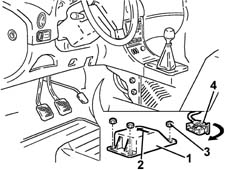
Location
The control unit is located under the centre console and is rigidly fixed to the bodyshell: in this way the deceleration sensors, located inside it, are close to the centre of gravity and detect the deceleration iof the entire vehicle accurately.| The control unit should always be fitted with the arrow facing the direction in which the vehicle is travelling. |
Control unit specifications
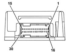
The control unit receives a 12 V supply with the ignition in the ON position, but it is capable of working for a further 220 msec approx. after the supply is cut off.This is possible thanks to the presence of a buffer condenser which accumulates sufficient electrical energy to produce the Air Bag activating signal.The operation of the system is thereby also guaranteed even if the impact causes a fall in the system voltage (e.g. battery damaged or broken, break in the supply cables, etc.).Whilst the vehicle is running, the electronic control unit continuously carries out the system fault diagnosis, checking the continuity of the circuit and the components.If a fault is detected it is memorized and the "Air Bag failure warning light in the instrument panel comes on.The fault memory can be consulted by connecting the diagnostic equipment (Examiner or S.D.C.) to the diagnostic socket, as described below.The control unit microprocessor carries out complex calculation algorhythms for the signal coming from the accelerometer sensor and determines the severity of the impact. According to the severity level and, with the go ahead of the safety sensor, a signal is sent to activate the Air Bags.This activation order is stored in a special crash memory which contains information relating to the exceeding of the intervention thresholds and the go ahead for the safety sensor.Control unit pin-out
-
ELECTRONIC CONTROL UNIT FOR SYSTEM WITH 6 CHARGES
An electronic control unit manages the entire system checking all the components and activating the systems (pretensioners, Air Bags, Side Bags), when necessary.Operation
There is a longitudinal electronic accelerometer sensor inside the control unit whose signal, suitably processed by a micropocessor, makes it possible to determine the severity of an impact and consequently decide whether or not to activate the pretensioners and Air Bags.A second longitudinal electro-mechanical sensor, which has a safety function, gives the go ahead for the activation.The control unit has two different levels of intervention for a frontal impact:
- at the first level only the pretensioners are activated
- at the second level both the pretensioners and the Air Bags are activated.
Location
The control unit is located under the centre console and is rigidly fixed to the bodyshell: in this way the deceleration sensors located inside it are close to the centre of gravity and detect deceleration for the entire vehicle accurately.| The control unit should always be fitted with the arrow pointing in the direction the vehicle is travelling in. |

Control unit specifications
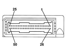
The control unit receives a 12 V supply with the ignition in the ON position, but it still operates for a further 220 msec approx after the supply is cut off.This is made possible thanks to the presence of two separate buffer condensers which accumulate sufficient electrical energy to produce the signal for activating the Air Bags and the Side Bags.The operation of the system is therefore guaranteed even if the impact causes a fall in the system voltage (e.g. battery damaged or broken, break in the supply cables, etc.).Whilst the vehicle is running, the electronic control unit continously carries out the system fault diagnosis, constantly checking the circuit and components.If a fault is detected it is memorized and the "Air Bag failure" warning light in the instrument panel comes on at the same time.The failure memory can be consulted by connecting the diagnostic equipment (Examiner or S.D.C.) to the diagnostic socket, as described below.The control unit microprocessor carries out complex calculation algorhythms for the signal coming from the accelerometer sensor and determines the severity of the impact. According to the severity and, with the go ahead of the safety sensor, it sends a signal to activate the Air Bags.This activation order is stored in a special crash memory which contains information relating to the exceeding of the intervention thresholds and the go ahead for the safety sensor.Control unit pin-out
-
| ... DATA ERROR - CROPPED TEXT | Ошибка данных - Текст обрезан ... |
|---|