3308467 - 1056B multi-point injection system (mpi) (Automatic transmission)
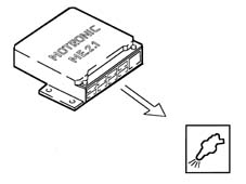
VIEW OF ASSEMBLY
-
GENERAL CHARACTERISTICS
Operation of the fuel injection-ignition
The Bosch Motronic ME2.1 system with a motorized butterfly belongs to the category of integrated systems with:
- ignition
- sequential and timed electronic injection.
The main operating principles of the sytem are basically as follows:
- self-learning;
- system self-adaptation;
- autodiagnosis;
- recognition of the Alfa Romeo CODE (Immobilizer);
- control of cold starting;
- control of combustion - Lambda sensor;
- control of detonation;
- control of mixture enrichment during acceleration;
- fuel cut-off with accelerator pedal released;
- fuel vapour recovery;
- control of the maximum rpm;
- control of the fuel pump;
- connection to the climate control system;
- recognition of cylinder position;
- control of optimum injection time for each cylinder;
- adjustment of ignition advance values;
- management of idle speed (also according to the battery voltage);
- management of the butterfly opening law (Sport throttle response);
- control of the electric fans;
- control of the Cruise Control system (where fitted)
- connection with the ABS control unit;
- connection with the automatic transmission control unit (where fitted);
- conection with the instrument panel.
Fuel injection system
The essential conditions that must always be met in the preparation of the air-fuel mixture for the correct operation of controlled-ignition engines are mainly:
- the "metering" (air/fuel ratio) should constantly be kept as close as possible to the stoichiometric ratio, so as to ensure the maximum conversion capacity for the catalytic converter (max. efficiency).
- the "homogeneity" of the mixture, consisting of petrol, diffused as finely and evenly as possible in the air.
The information processed by the control unit for controlling optimum metering is received in the form of electrical signals emitted by the:
- air flow meter and air temperature sensor, for the exact quantity of air drawn in
- rpm sensor, which generates an alternating single-phase signal whose frequency indicates the engine rpm
- butterfly potentiometer, to recognize the acceleration conditions requested
- coolant temperature sensor located on the thermostat
- Lambda sensor for determining the oxygen content in the exhaust gases.
Ignition system
The ignition is of the inductive discharge type, distributorless, with power modules located in the fuel injection control unit.The system has a single coil for each plug (MONOCOIL); the advantages of this solution are:
- less electrical overload;
- guaranteed constant discharge on each plug.
The control unit corrects the advance values mainly in accordance with the:
- engine coolant temperature
- intake air temperature
- detonation.
The information the control unit processes in order to drive the single coils is received in the form of electrical signals emitted by the:
- air flow meter and air temperature sensor, for the exact quantity of air drawn in
- rpm sensor, which generates an alternating single-phase signal whose frequency indicates the engine rpm
- detonation sensors (on the upper part of the cylinder block/crankcase between the two heads) to recognize the cylinder where detonation is occurring and correct the ignition advance
- butterfly potentiometer, to recognize the minimum, partial and full load conditions
- timing sensor.
OPERATION
Diagram of input/output information to/from the control unit
-
SYSTEM OPERATING LOGICS
Self-learning
The control unit implements the self-learning logic in the following conditions:
- removing-refitting or replacement of the injection control unit
- removing-refitting or replacement of the butterfly casing integrated with D.V.L.

System self-adaptation
The control unit has a self-adaptation function which recognizes changes in the engine which occur as a result of bedding-in and ageing processes of both components and the engine itself.There are two adaptation functions according to two intervention plans: minimum and usage.
Autodiagnosis
The control unit's self-test checks the signals coming from the sensors, comparing them with the permitted limits:
- indication of starting faults
- warning light on for 4 secs indicates test stage
- warning light off after 4 secs indicates no faults in components that could affect the values established in emission control regulations
- warning light on after 4 secs indicates fault
- fault indication during operation
- warning light on indicates fault
- warning light off indicates no faults in components that could affect the values established in emission control regulations
- recovery
- the control unit defines as and when required the type of recovery depending on the faulty components
- the recovery parameters are managed by non-faulty components.
Recognition of the alfa romeo code
When the control unit receives the ignition "ON" signal, it dialogues with the Alfa Romeo CODE control unit to obtain starting enablement.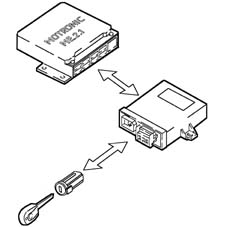
Check on cold starting
The following occurs during cold starting:
- natural weakening of the mixture because of poor turbulence of the fuel particles at low temperatures
- condensation of the fuel on the inner walls of the inlet manifold
- higher viscosity of the lubricating oil.
The electronic control unit recognizes this condition and corrects the fuel injection times in accordance with:
- coolant temperature
- intake air temperature
- battery voltage
- engine rpm

Check on combustion - lambda sensor
According to the engine speed and load, the control unit processes the Lambda sensor signal using a special integrator and corrects the injector opening times.
Control of detonation
The control unit can delay the ignition selectively at the cylinder required, according to the combination of figures received from the detonation and timing sensors and:
- reduces the ignition advance in steps of 3° up to a maximum of 9°
- updates the threshold value to take into account:
- background noise;
- ageing of the engine.
With the auto-adjustment function, the control unit:
- memorizes the various advance reductions, continuously repeated;
- adapts the map to the different engine conditions.
Recovery:
- in the case of fault with the timing sensor or the detonation sensor or the injection control unit, the ignition is delayed according to the engine temperature and speed. The maximum ignition delay is always below 9° engine.

Control of the mixture enrichment during acceleration
If there is a request for considerable acceleration, the control unit modifies the injection time and the butterfly position.Recovery:
- the control unit replaces the signal coming from the faulty air flow meter with the signal from the potentiometer integrated in the butterfly casing integrated with D.V.L.

Fuel cut-off with the accelerator pedal released
The control unit, in the following conditions:
- recognition of idle condition
- engine speed above a certain threshold
de-activates the fuel injection according to the:
- number of revs
- engine temperature
- vehicle speed.

Fuel vapour recovery
The (polluting) fuel vapours, collected in an activated-charcoal filter (canister), are sent to the inlet ducts to be burnt.This takes place via a solenoid valve operated by the control unit which keeps it closed for 60 seconds after starting after which it keeps it open for 90 seconds.During this period (90 seconds), the Lambda sensor measures the carburation which is compared by the control unit with the basic map.If there are no variations, the control unit closes the solenoid valve, otherwise it keeps it open for a further 90 seconds allowing the washing of the canister.Nominally, the filter washing flow rate is limited to a small percentage of the air flow rate meter reading so that the adjustment plan is as balanced as possible and the driveability of the vehicle is disturbed as little as possible.
Control of the maximum rpm
Depending on the rpm reached by the engine, the control unit:
- over 6800 rpm cuts off the supply to the injectors (it is allowed to reach a maximum of 7000 rpm for a maximum of 5 secs).
- below 6600 rpm it restores the operation of the injectors.

Control of fuel pump
The con
| ... DATA ERROR - CROPPED TEXT | Ошибка данных - Текст обрезан ... |
|---|
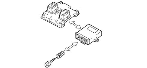
CONSTRUCTION FEATURES
View of assembly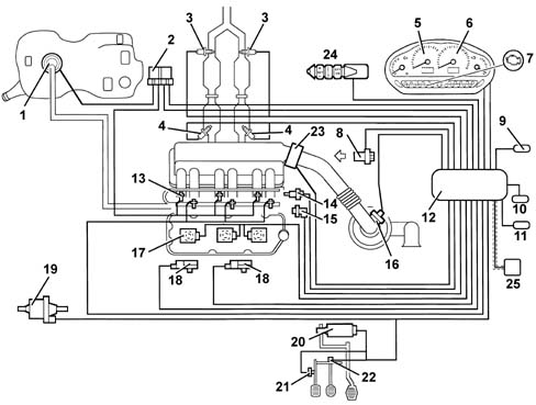
GENERAL CHARACTERISTICS
Operation of the injection/ignition system
The Bosch Motronic ME3.1 system with a motorized throttle belongs to the category of integrated systems with:
- ignition
- sequential and phased electronic injection.
The main operating principles of the sytem are basically as follows:
- self-learning;
- system self-adaptation;
- autodiagnosis;
- recognition of the Alfa Romeo CODE (Immobilizer);
- control of cold starting;
- control of combustion - Lambda sensor;
- control of knock;
- control of mixture enrichment during acceleration;
- fuel cut-off with the accelerator pedal released;
- fuel vapour recovery;
- control of the maximum rpm;
- control of the fuel pump;
- connection to the climate control system
- recognition of cylinder position;
- control of the optimum injection time for each cylinder;
- adjustment of ignition advance values;
- management of the idle speed (also according to the battery voltage);
- control of the electric fans;
- control of the Cruise Control system (where fitted);
- connection with ABS control unit;
- connection with the automatic transmission control unit (where fitted);
- connection with the instrument panel;
- fuel system diagnosis;
- catalyzer diagnosis;
- detection of misfire;
- Lambda sensors diagnosis.
The essential conditions that must always be met in the preparation of the air-fuel mixture for the correct operation of controlled-ignition engines are mainly:
- the 'metering' (air/fuel ratio) should constantly be kept as close as possible to the stoichiometric ratio, so as to ensure the maximum conversion capacity for the catalytic converter (max. efficiency).
- the 'homogeneity' of the mixture, consisting of petrol, diffused as finely and evenly as possible in the air.
The information processed by the control unit for controlling optimum metering is received in the form of electrical signals emitted by:
- air flow meter and air temperature sensor, for the exact quantity of air drawn in
- rpm sensor, which generates an alternating single-phase signal whose frequency indicates the engine rpm
- throttle potentiometer, to recognize the driver conditions requested
- coolant temperature sensor located on the thermostat
- Lambda sensors for determining the oxygen content of the exhaust gases.
The system has a single coil for each plug (MONOCOIL); the advantages of this solution are:
- less electrical overload;
- guarantee of constant discharge at each spark plug.
The control unit corrects the advance values mainly in accordance with:
- engine coolant temperature
- intake air temperature
- detonation.
The information which the control unit processes to operate the ignition coils is received by means of electrical signals emitted by the:
- air flow meter and air temperature sensor, for the exact quantity of air drawn in
- rpm sensor, which generates an alternating single-phase signal whose frequency indicates the engine rpm
- detonation sensors (on the upper part of the cylinder block/crankcase between the two heads) to recognize the cylinder where detonation is occurring and correct the ignition advance
- throttle potentiometer, to recognize the minimum, partial and full load conditions
- timing sensor.
OPERATION
Diagram of input/output info to/from control unit
System operating modes
Self-learningThe control unit implements the self-learning mode in the following conditions:
- removing-refitting or replacement of the injection control unit
- removing-refitting or replacement of the throttle body integrated with D.V.L.
- removing-refitting or replacement of the rpm sensor/flywheel for recognizing misfire.


The (MIL) warning light operating logic is as follows:
- with the ignition key in the ON position, the warning light comes on and remains on until the engine has been started up. The control unit's self-test checks the signals coming from the sensors, comparing them with the permitted limits:
Signalling of faults during engine starting:
- the failure of the warning light to go out after the engine has been started up means that there is an error memorized in the control unit.
Fault indication during operation
- the warning light flashing indicates possible damage to the catalyzer due to misfire.
- the warning light on constantly indicates the presence of engine management errors or EOBD errors.
| For some markets the warning light is read (rather than amber) and the EOBD is not active, and the warning light only signals faults in the fuel injection system as in the preceding versions. This is achieved with a specific engine management control unit (not interchangeable with the others) with modified software so as not to have the EOBD function. |

In cold starting conditions there is a natural weakening of the mixture which causes poor evaporation of the fuel at low temperatures:
- condensation of the fuel on the inner walls of the inlet manifold
- increased viscosity of the lubricant oil.
The electronic control unit recognizes this condition and corrects the fuel injection time in accordance with:
- coolant temperature
- intake air temperature
- battery voltage
- engine rpm.


The control unit can delay the ignition selectively at the cylinder required, according to the combination of figures received from the detonation and timing sensors and:
- reduces the ignition advance in steps of 3° up to a maximum of 9°
- updates the level to take into account background noise and ageing of the engine.
With the auto-adjustment function, the control unit:
- memorizes the various advance reductions, continuously repeated;
- adapts the map to the different engine conditions.


The control unit with:
- recognition of idle condition
- engine speed above a certain threshold
de-activates the fuel injection according to the:
- engine rpm
- engine temperature
- vehicle speed.
| ... DATA ERROR - CROPPED TEXT | Ошибка данных - Текст обрезан ... |
|---|