3308511 - 2130B automatic transmission components (Automatic transmission)
OIL PUMP
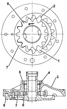
It is the geared type and is fitted between the torque converter and the gearbox casing and is controlled by the converter pump impeller (6).The oil, under pressure, engages the gears and lubricates the various gears.The pump is made up of two eccentric gears:
- drive gear (7) with outer teeth
- driven gear (8) with inner teeth.
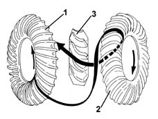
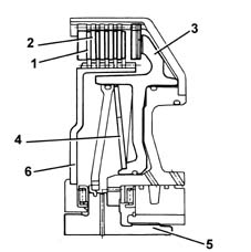
TORQUE CONVERTER
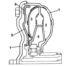
It is fitted between the engine and the gearbox in place of the conventional disc clutch.The torque converter is designed to ensure a soft (hydraulic) connection between the engine and the gearbox.The torque converter consists of:
- a casing (1) containing the oil and the various components
- a pump impeller (2) connected to the crankshaft and to the oil pump
- a turbine impeller (3) connected to the gearbox input shaft
- a stator (4), fitted on the free wheel, which has the task of directing the flow of oil to the pump impeller
- a torque converter lock-up device (5) operated by the CAE control unit via a solenoid valve (MV2) and a regulation valve (REG3).
- a clutch cover (6).
The converter operates in two stages:
- converter stage, where it multiplies the torque
- coupler stage, where it transmits the torque with an efficiency of 98% or 100% according to whether or not the lock-up is activated.
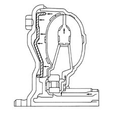
Torque converter operation
As soon as the engine is started up, the pump impeller behaves like a centrifugal pump and the oil is thrust by the centrifugal force into the radial ducts.The oil comes out of the pump impeller vanes, is directed to the turbine impeller where it flows through the ducts from the edges towards the centre.If the oil were to flow directly to the pump impeller it would meet the impeller vanes in the opposite direction to the direction of rotation.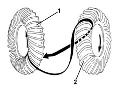
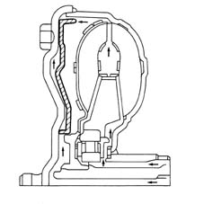
Coupling operation (lock-up)
If the oil were the only element transferring torque, there would always be a difference in the number of revs between the pump and turbine impellers known as "creeping".In reality, the torque converter is fitted with a device managed by the CAE control unit via a regulation valve (REG3) and a solenoid avlve (MV2).The latter, reversing the flow of the oil in the converter, activates a clutch between the engine drive plate and the turbine.There are three operating stages:
- open state (see torque converter operation)
- closed state: the torque is transmitted entirely by the engine to the gearbox; the control unit prevents any sliding between the pump and the turbine.
CLUTCHES
There are two, oil bathed clutches comprising, alternately:
- driven discs (2) covered in a high friction coefficient material
- drive discs (1) made from steel.
BRAKES
There are three, oil bathed multiple discsThe operation is basically the same as the clutches.The only difference is that the drive discs do not transmit torque to the driven discs because the latter are fixed to the gearbox casing.The effect is therefore to brake the rotation of the drive discs and consequently the gear involved.EPICYCLIC ASSEMBLY
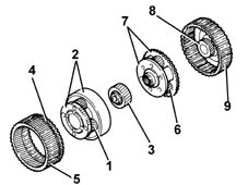
This is made up of two simple epicyclic assemblies fitted directly behind one another and couplied.The epicyclic assembly consists of:
- first epicyclic satellite gears (1)
- first epicyclic satellite carrier (2)
- first epicyclic pinion (3)
- first epicyclic ring gear (4)
- ratio reduction pinion (5)
- second epicyclic satellite gears (6)
- second epicyclic satellite carriers (7)
- second epicyclic pinion (8)
- second epicyclic ring gear (9)
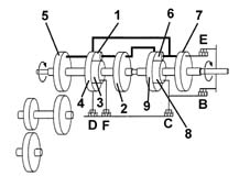
Activation of brakes/clutches according to the speed engaged:
- R: clutch B and brake D activated
- D1: clutch B and brake F activated
- D2: clutch E and brake F activated
- D3: clutches E and B activated
- D4: clutch E and brake C activated
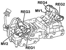
ELECTRO-HYDRAULIC UNIT
The electro-hydraulic unit regulates and distributes the oil pressure at the brakes and the clutches to engage the desired ratio.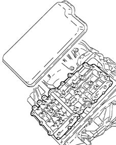
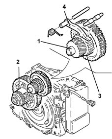
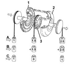
INTERMEDIATE SHAFT WITH PARKING LOCK
The intermediate shaft (1) is fitted on bearings and is designed to transfer power from the epicyclic assembly to the differential (2).A straight toothed wheel (3) is positioned between the two intermediate shaft gears and allows the shaft to be immobilized by means of a locking device when the gear selector lever is in position P.It is impossible to enage the parking lock device accidentally when the vehicle is being driven at high speed because the device (4) slides on the wheel (3) teeth.| Do not repeatedly engage P when the vehicle is being driven to avoid wear of the parking lock device. |