3315487 - Introduction - GEARBOX (Automatic transmission)
The ZF 4HP20 Sportmatic gearbox is totally
automatic with electro-hydraulic operation and 4 forward speeds
plus reverse.An electronic control unit manages:
- the torque converter
- the gear changes
- the specific programmes.
The Sportmatic solution allows the driver
to also use the vehicle in sequential, manual conditions as well
as completely assisted in the auto-adjustment operation mode.The gearbox is equipped with a hydro-dynamic
torque converter with an anti-slip device which allows demultiplication ratios.The 2.6 V6 and 3.0 V6 versions differ through
the gearbox ratios and through the different electronic control
unit management software.A feature of this gearbox is that
it perates without a free wheel because the gear change takes place
by overlapping the couplings which allows:
- improved compactness and more lightweight
- improved efficiency due to the reduction in friction
- lower torque points for the components and kinematic chain.
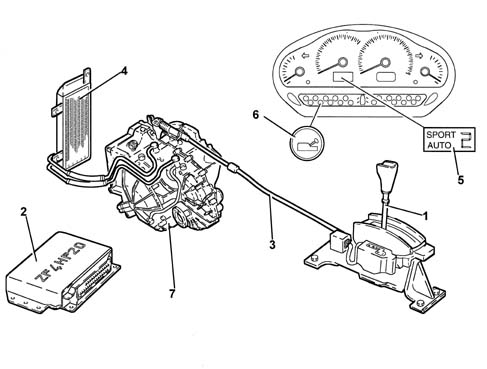
VIEW OF ASSEMBLY
-
1, Gear selector lever
2, Electronic control unit
3, Gear control cable
4, Hydraulic circuit cooling radiator
5, Gear position indicator
6, System failure/oil temperature warning light
7, Automatic transmission
DESCRIPTION
General characteristics
The electronic management of the gearbox
makes it possible to produce flexible gear shifts as appropriate.The control unit has the task of:
- adjusting the oil pressure to the engine torque for gear
changes
- implementing the safety functions
- defining the gear change programme
- carrying out the system fault diagnosis.
The control unit uses the following
signals for the management of these logics:
- engine rpm (through the injection control unit)
- butterfly position (through the injection control unit)
- engine temperture (through the injection control unit)
- converter turbine speed
- gearbox output rpm
- vehicle speed (A.B.S.)
- gearbox oil temperature
- gear selector lever position
- accelerator pedal position (kick-down, through the injection
control unit)
- brake pedal position (A.B.S.)
In addition, the control unit converses,
through the CAN line (Controller Area Network), with the A.B.S.
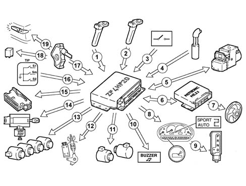
control unit and the injection/ignition control unit.DIAGRAM OF INPUT/OUTPUT INFORMATION TO/FROM THE CONTROL
UNIT
-
1, Input shaft rpm sensor
2, Output shaft rpm sensor
3, Driver's door switch
4, Gearbox oil temperature sensor
5, A.B.S. control unit / CAN line
6, Injection-ignition control unit / CAN line
7, Water/oil cooling fan
8, Instrument panel
9, Gear lever position LED cowling
10, Buzzer
11, Solenoid valves MV1 and MV2
12, Release for lever in "P"
13, Pressure regulators (REG1 - REG2 - REG3 - REG4)
14, Key lock
15, Diagnostic socket
16, Switch on gear lever for recognizing auomatic/manual management
17, Selector lever position sensor (P - R - N - D)
18, Starting go ahead
19, Reversing lights
OPERATING LOGICS
Ags adapation management
Thanks to the signals received from
the injection control unit and the ABS control unit (through the
CAN line), the automatic transmission control unit is capable of
making an autonomous selection of the:
- optimum gear change programme (shift programme)
- suitable gear.
Usage conditions analyzed by the control unit
The control unit analyzes each individual
vehicle usage condition, distinguishing it on the basis of the signals
received from the various sensors.The following conditions are analyzed:
- starting (accelerator pedal/potentiometer position/speed
variation)
- acceleration (accelerator pedal/potentiometer depression
speed)
- full load (number of engine kid-down full load signals
or position maintenance time)
- braking (release speed of accelerator pedal and intervention
of braking system)
- type of programme (gear selector lever position)
- winter driving (slipping of drive wheels/ABS active sensors)
- driving with a trailer or uphill (vehicle speed dependent
on the torque transmitted)
- entering a bend (transverse acceleration detected by the
difference in rotation of the wheels on the two sides/ABS active sensors)
- driving downhill (vehicle acceleration dependent on the
accelerator pedal/potentiometer position)
- driving in town or in traffic (acceleration pedal/potentiometer
position and vehicle speed)
- gear requested by the driver (gear selector lever position)
- cold starting (engine temperature).
Gear change management programme (shifting programme)
The control unit contains programmes
in its memory for optimizing the gear the vehicle is in:
- automatic (DSP)
- automatic sports
- manual (TIP)
- winter (WNT)
- warm-up (WML)
- high oil gearbox temperature safety (SKT)
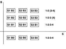
Automatic programme (dsp)
The automatic driving mode consists
of 12 gear change programmes divided into 3 main groups:
- low sports (S1)
- medium sports (S2)
- high sports (S3).
The remaining 4 divisions in these
groups are:
- downhill road (B0)
- flat road (B1)
- uphill road (B2)
- steep uphill road (B3)
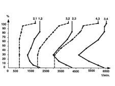
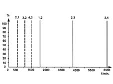
The gearbox control unit, according
to the:
- vehicle speed
- torque transmitted
recognizes the inclination of the road surface
(B0) and, on the basis of the sports drive setting (S), autonomously
selects the most suitable programme for the situation.B, Road gradientS, Sports level( ), Condition considered by the software,
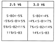
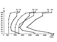
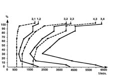
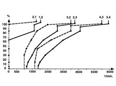
but in reality not achievedOn the basis of the engine type, there are
different road gradient thresholds for selecting the various programmes
automatically."High sports" downhill graph (S3
B0)"Medium sports" downhill graph
(S2 B0)"Low sports" downhill graph (S1
B0)"High sports" flat road graph
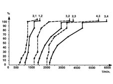
(S3 B1)"Medium sports" flat road graph
(S2 B1)"Low sports" flat road graph (S2
B0)"High sports" uphill graph (S3
B2)"Medium sports" uphill graph (S2
B2)"Low sports" uphill graph (S1
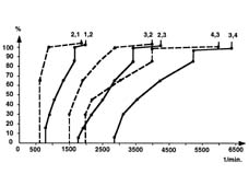
B2)"High sports" steep uphill graph
(S3 B3)"Medium sports" steep uphill graph
(S2 B3)"Low sports" steep uphill graph
(S1 B3)For each main group there are a further
15 additional operating curves for adjustment to the operating situation:
- 3 up-shift programmes for changing to a higher gear
- 3 down-shift programmes for changing to a lower gear
- 9 lock-up management programmes (2 - 3 - 4)
Lastly, each lock-up programme possesses
a further eight data points and an additional kick-down point.When operating automatically and with the
lever in the Drive position, the programme allows a double down-shift
simply by fully depressing the accelerator pedal in 0.1 seconds.Whilst changing gear, the CAE control unit
requires a momentary reduction in torque from the injection control
unit. The duration of this request is calculated by the CAE control
unit starting from the turbine rotation speed (input shaft inductive rpm
sensor).Automatic sports operation
In these circumstances, the electronics
favour a sports gear change management. With this in mind, the software
uses programmes which reflect this logic.The choice is restricted to the following
programmes.Medium sports:
- S2 B2 uphill road
- S2 B3 steep uphill road
High sports:
- S3 B2 uphill road
- S3 B3 steep uphill road
These programmes are also used in automatic
management (Drive) with different selection thresholds where it
would be very difficult for the electronics to select sports programmes.In automatic sports operation these selection
thresholds are less "strict".Manual operation (tip)
The Tip function allows the manual use of
the gearbox.by moving the gear selector lever:
- forwards (+) the change is to a higher gear (up)
- backwards (-) the change is to a lower gear (down).
There is only one change for each request:
it is not possible to accumulate the request.The control unit inhibits gear change requests
if the gearbox output shaft speed (output shaft inductive rpm sensor)
is not between certain limits to avoid the engine speed being too
high or too low.Winter programme (wnt)
This programme is engaged automatically
depending on the slipping of the drive wheels (ABS active sensors)
and requires a learning time of around 0.3 seconds.On the basis of specific curves, it makes
provision for gear shifts 2, 3, 4 and viceversa.This programme does not allow starting in
1st speed.Warm up programme (wml)
This is a programme derived from a special
configuration of the "SKT" programme which helps the engine
reach operating temperature quickly raising the gear change points
(sports logic) according to the temperature of the engine.It is activated, after starting, if the
temperature of the engine coolant is below 30° ? a?d ?eµa??s
a?t??ated ?p t? 34° ?.High gearbox oil temperature safety programme (skt)
This programme is activted when the temperature
of the gearbox oil reaches 120° ? a?d ?eµa??s a?t??ated
?p t? 117° ?.Up shift and down shift gear change inhibition
functions have been introduced into this programme.It is, however, position to engage and use
the TIP manual programme.The CAE control unit implements for
the following strategies to facilitate the cooling of the gearbox
oil:
- it activates the lock-up clutch to reduce the Jaule effect
in the converter
- it sends oil temperature information, via the CAN line,
to the injection control unit for the management of the cooling
fan (not used by the injection control unit).
Safety functions
Inhibition of gear changes round bends
The control unit inhibits a change to a
higher gear if there is strong transverse acceleration (bend) with
the accelerator pedal released very rapidly. The system maintains
the last ratio selected.The system automatically restores the automatic
programme when the critical period is over.This strategy affords:
- better vehicle equilibrium
- prompt acceleration coming out of the bend because the
vehicle finds itself in the ideal gear.
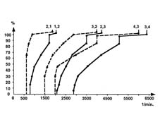
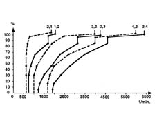
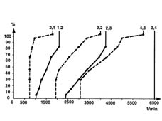
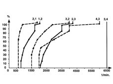
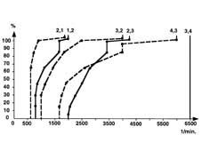
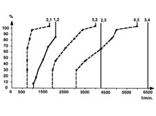
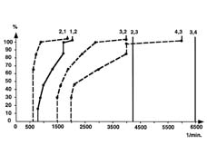
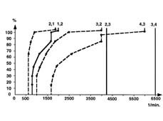
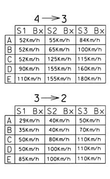
Change to a lower gear (down shift) whilst braking
In the case or emergency or rapid braking,
the control unit selects the lowest permissible gear to achieve
the maximum engine braking effect.This depends on the:
- type of braking
- gradient of the road
- type of driving (sports level).
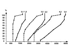
The tables below illustrate gear changes
4-3 and 3-2 (down shifts) on the basis of the vehicle speed.
A, Repeated braking
B, Gentle braking
C, Medium braking
D, Strong braking
E, Emergency braking
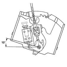
Shift-lock
A system locks the gear selector lever when
it is in position P until the brake pedal and the button on the
gear lever grip are pressed with the ignition in the ON position.If the case of a failure, there is a manual
release safety device, located at the side of the centre tunnel
(passenger side). A rubber plug must be removed to gain access to
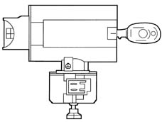
this device.Key-lock
The key can only be removed from the ignition
with the gear selector lever in position P for a maximum of 25 seconds
after the key off.If there is a failure, there is a manual
release safety device, located under the ignition lock barrel.Buzzer
A special buzzer, located in the LED cowling
on the gear lever, warms the driver for a maximum of 15 seconds
whilst the driver's door is opened that the gear selector lever
is not in position P.Outside of revs
This function is designed to prevent damage
to the engine through too high a rotation speed.The CAE control unit sets a higher gear
before an excessive speed is reached or prevents (delays) the shift
to a lower gear to avoid a similar risk condition.Starting
The engine can only be started up with the
selector lever in position "N" or "P".Reverse
With the selector lever in position "R",
reverse gear will not be engaged if the vehicle speed is above a
pre-set level.When the sp| ... DATA ERROR - CROPPED TEXT | Ошибка данных - Текст обрезан ... |
|---|