3308518 - 3340A abs check/adjustment devices
ELECTRO-HYDRAULIC UNIT
It consists of an electronic control unit (1) and an electro-hydraulic control unit (2).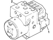
Electronic control
The electronic control unit is responsible for:
- acquiring the data coming from the 'active' wheel rpm sensors
- storing control parameters defined during the preparation of the vehicle
- storing the control software
- processes downloaded data
- controls the braking process
- detecting failures at the braking system components
- memorizing the fault codes and activating the A.B.S. and EBD warning lights.
- transmitting and receiving data via the diagnostic connector
- conversing with the injection and CAE control units via the CAN line (only for versions with automatic transmission).
Hydraulic control unit
The electro-hydraulic control unit consists of:
- eight two-way solenoid valves
- a dual circuit electric recovery pump
- two low pressure accumulators
- two high pressure accumulators
Responsible for modulating the pressure of the fluid at the brake calipers via two solenoid valves with the following stages:
- brake fluid pressure increase
- brake fluid pressure maintenance
- brake fluid pressure discharge.
The letters indicating to which caliper and to which brake pump outlet they should be connected are stamped on the control unit at each outlet.
- RR = to the right rear brake (pipe marked with a light blue coloured band)
- LR = to the left rear brake (pipe marked with a green coloured band)
- RF = to the right front caliper (pipe marked with a yellow coloured band)
- LF = to the left front caliper (pipe marked with a white coloured band)
- MC1 = from the T connector (pipe marked with a black or pink coloured band when the pipe polyamide resin is black)
- MC2 = from the secondary circuit pump/front.
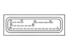
Pin out
-
ACTIVE SENSORS
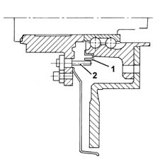
They consist of two basic elements:
- a magnetic multi-polar codifier (1) integrated in the 'instrument' wheel hub bearing
- a 'magnetic-resistive' receiver (2) opposite the codifier.
The adoption of active sensors offers the following advantages:
- it reduces sensitivity to electro-magnetic interference
- it saves weight and size
- it simplifies the transmission couplings through the elimination of the phonic wheels.
Front active sensors
-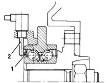
Rear active sensors
-