3315498 - Introduction - AIR CONDITIONING CASING AND COMPONENTS
CLIMATE
CONTROL WITH AUTOMATIC TEMPERATURE CONTROL
Presentation
The climate control system is the
following type:
- automatic temperature - ventilation - distribution control
- with recirculation
- with direction of the flows.
The user can select the desired air flow
and temperature.A special control unit manages the operation
of the system.The control unit implements the thermaladjustment
according to the signals received from the:
- outside air temperature sensor
- inside air temperature sensor
- vent outlet treated air temperature sensors
- solar radiation sensor
According to the signals received,
operates the following are operated to reach and maintain a comfortable
temperature inside the passenger compartment:
- mixture actuator
- recirculation actuator
- distribution actuator
- electric fan
- compressor.
In addition, the control unit operates the
heated rear windscreen via the integrated services control unit.The climate control system basically
consists of:
- air intake unit
- air filter unit
- electric fan
- air conditioning unit
- mixture unit
- heater unit
- distribution unit.
1, Air conditioning compressor
2, Air conditioning condenser
3, Drier filter
4, Expansion valve
5, Evaporator unit
6, 4 stage pressure switch
7, Outside air temperature sensor
8, Solar radiation sensor
Air intake unit
The air intake unit makes it possible
to:
- let outside air enter the passenger compartment
- circulate the air inside the passenger compartment.
An actuator, controlled by the control unit,
moves the air intake flap into the two different positions.Air filter unit
This consists of a filter which
makes it possible to reduce pollution, pollen and some unpleasant
odours.Ventilation unit
This consists of a brushles motor
which, depending on the voltage applied to the inlet circuit, regulates
the speed of the fan and consequently the air flow rate.Air conditioning unit
It consists of:
- a compressor
- an expansion valve
- an evaporator
- a condenser
- a drier filter
- pipes
- a 4 stage pressure switch
It makes it possible to cool and/or dehumidify
the air introduced into the passenger compartment.Mixture unit
It consists of special flaps
and ducts which allow the temperature of the air introduced into
the passenger compartment to be controlled.Heater unit
It consists of a radiator supplied
by the engine coolant which allows the air introduced into the passenger
compartment to be heated.Distribution unit
It consists of a series of flaps
and ducts with special vents.It allows the air to be distributed to the
various parts of the passenger compartment.Climate control controls
The user interface, integrated in
the ICS system, for the climate control system consists of:
- controls
- a monitor with a colour display.
The climate control system controls appear
on a single page by pressing the "CLIMA" button.The following are displayed:
- internal temperature set (in ° C or in °F)
- fan setting symbol
- air distribution symbol (windscreen, centre of vehicle,
floor)
- defrost symbol (defrost ventilation activated/deactivated)
- recirculation symbol (recirculaion activated/deactivated)
- "MANUAL" or "AUTO" or "FULL AUTO"
warning for modification of manual setting or automatic operation.
Operating logics
Starting transition
This logic is designed so as
not to create problems for the user (cold air jets and/or demisting
of the front window) in certain temperature conditions during starting.During the starting transition with
"FULL AUTO" operation, the following functions are implemented:
- initial air distribution to "FLOOR" and then
"DEF"
- air mixture flap completely open (maximum heat)
- recirculation air flap in "dynamic air" position
- compressor enabled
- increasing variation in the air flow rate until a level
calculated by the control unit is reached.
This logic is interrupted by possible
requests for:
- maximum cold (LO)
- maximum heat (HI)
- defrost (FRONT).
Maximum heat request (hi)
This is activated by setting
a temperature value above 28° C corresponding to "HI".To satisfy this requirement the system
exits from the automatic control of the thermal adjustment ((FULL
AIUTO) and modifies the system functions as described below:
- air mixture flap completely open (maximum heat).
- automatic air distribution: distribution flaps in "FLOOR"
position
- manual air distribution: position of distribution flaps
dependent on the preselected setting.
- automatic ventilation: maximum permissible flow rate
- manual ventilation: with flow rate corresponding to that
preselected.
The interruption of the ventilation function
takes place when the key is turned to the OFF position, or when
the "OFF" button is operated or when the "defrost"
button is operated.Maximum cold request (lo)
This is activated by setting
a temperature value below 16° C corresponding to "LO".To satisfy this requirement the system
exits the automatic thermal adjustment control (FULL AUTO) and modifies
the system functions as follows:
- air mixture flap completely closed (maximum cold)
- automatic air distribution: distribution flaps in "VENT"
position
- manual air distribution: distribution flaps position dependent
on the preselected setting.
- automatic ventilation: maximum permissible flow rate
- manual ventilation: flow rate corresponding to that preselected.
- recirculation: air intake flap forced into recirculation
position.
The interruption of the recirculation function
occurs if the ignition is turned to the OFF position or if the "OFF"
button is operated or if the "defrost" button is operated.Defrost request
It is activted using the "FRONT"
button and manages the air flow rate depending on the temperature
of the treated air coming out of the vents designed to demist the
windows inside the passenger compartment.The management of the defrost involves
the system functions as described below:
- compressor enabled.
- air distribution initially to "FLOOR" and then
"DEF".
- air mixture flap completely open (maximum heat)
- Ventilation: the management of the automatic air flow
rate depends on the temperature of the treated air.
- recirculation: the air intake flap is forced into the
dynamic position.
- heated rear windscreen management: the heated rear windscreen
is activated by the integrated services electronic control unit,
in accordance with an operating logic (see DESCRIPTIONS AND OPERATION:
Integrated multiservices control unit - 5505).
This function is interrupted by operating
the "OFF" button. | The defrost function has priority
over the following request: |
- maximum cold (LO)- maximum heat (HI)."full-auto" operation request
The completely automatic thermal
adjustment control is implemented by pressing the AUTO button with
the temperature setting between 16° C and 28° C."auto" operation request
The partial thermo-dynamically controlled
thermal adjustment is implemented by:
- pressing the AUTO button with the temperature setting
between 16° C and 28° C and
- modifying one of the following parameters: air flow rate,
air distribution and recirculation.
This function is interrupted by operating:
- the "OFF" button
- by the maximum heat request (HI)
- by the maximum cold request (LO)
Compressor engagement
The compressor is enabled with the:
- evaporator temperature close to 5 ° C
- defrost function selected
- recirculation function switched off and outside temperature
above 5 ° C.
The compressor is disabled with the:
- recirculation function engaged and the outside temperature
below - 5 ° C
- recirculation function switched off and the outside temperature
3 ° C.
The compressor can also be switched off
by operating the multi-stage pressure switch controlling the circuit
or by the injection/ignition control unit (see DESCRIPTIONS AND
OPERATION: Injection/ignition system - 1056).System components
Duct/distributor unit
This consists of three modules which
inside contain:
- the electric fan
- the evaporator
- the heater radiator
- Upper mixed air temperature sensor
- Lower mixed air temperature sensor
All the flaps are operated by special actuators
controlled by the control unit.
1, Electric fan
2, Evaporator
3, Heater radiator
4, Upper mixed air temperature sensor
5, Lower mixed air temperature sensor
6, Outside/recirculation air flap actuator
7, Air distribution flaps actuator
8, Mixed air flaps actuator
9, Combined filter element
Air distribution
1, Intake/recirculation air flap
2, Electric fan
3, Evaporator
4, Heater radiator
5, Mixed air flap
6, Air distribution flap
A, Recirculation air flow
B, Outside air flow
C, Windscreen/side windows air flow
D, Centre and side vents air flow
E, Lower and rear vents air flow
Electric fan
The ventilation unit is made
up of a brushless type direct current motor which, by means of the
voltage applied to the intake circuit, makes it possible to control
the fan speed and consequently the air flow rate using a PWM signal.The lack of brushes and commutator
allows:
- a reduction in inertia and wear
- the lack of electrical and mechanical leaks
- improved reliability, power and acceleration for the same
torque.
The absence of the commutator eliminates
problems of discharges between the terminals; the function of the
commutator is carried out by an external electronic switching circuit
which produces the current in the induction winding.There are less vibrations with this type
of motor and lower consumption than compared with traditional linear
control motors.
1, Electronic components inserted in an impermeable system
2, Card for electronics and connections
3, Support for motor and semiconductor heat dissipator
4, Centrifugal fan with high output and low noise
5, Motor cooling fan
6, Rotors with ferrite magnets
7, Laminated stator and winding
Combined filter element
The air introduced into the passenger
compartment from the outside passes through a combined filter, i.e.
consisting of two layers:
- the first "particle" layer has the task of trapping
the small particles of fine dust and pollen
- the second "active charcoal" layer is designed
to trap certain pollutant elements (odours) in the atmosphere.
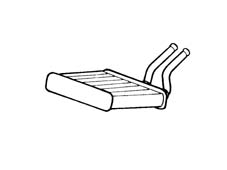
Heater radiator
This is a heat exchanger connected
to the engine cooling circuit by means of special pipes: - one draws
in hot water from the engine and allows the heating of the air introduced
into the passenger compartment- one allows the return of the coolant to
the engine.Outside/recirculation air flap actuator
This activates the rotation of
the outside/recirculation air flap in the two extreme position "dynamic
air" and "recirculation" without an intermediate
position, through the command received from the electronic control
unit.A motor controls the rotary movement of
a drive pin which acts directly on the flap.It receives a 12 V supply and if the polarity
is reversed, it is possible to rotate it in a clockwise or an anti-clockwise
direction.The actuator is not fitted with a feedback
potentiometer and therefore it is controlled by the control unit
by checking the current absorption.Air distribution flaps actuator
This operates the rotation of
the two air distribution flaps according to the command from the
electronic control unit.A motor controls the rotary movement of
a drive pin which acts directly on the flaps if supplied with a
variable duty-cycle signal.A potentiometer detects the effective position
and acts with feedback to the control unit checking the complete
travel between the extreme positions.Mixed air flaps actuator
It operates the rotation of the
two mixed air flaps according to the command from the electronic
control unit.A motor controls the rotary movement of
a drive pin which acts directly on the mixture flaps if supplied
with a duty-cycle signal.A potentiometer detects the effective position
and acts with feedback to the control unit checking the| ... DATA ERROR - CROPPED TEXT | Ошибка данных - Текст обрезан ... |
|---|
Air conditioner compressor
A Denso 6Ca17 variable capacity (6 cylinder)
compressor is fitted on this version.It consists of two main sections:
- the compressor casing (1)
- the clutch assembly (2)
A, Clutch assembly fixing bolt
B, Hub
C, Pulley retaining circlip
D, Pulley
E, Solenoid pulley circlip
F, Solenoid
G, Scraper rings for adjusting clutch clearance
H, Earth connection cable
I, Solenoid supply cable
The flow rate is adjusted by varying the
piston stroke according to the angle of the oscillating disc.The angle of the oscillating disc is controlled
by the regulating valve, which varies the internal pressure (Pc)
of the compressor on the basis of the inlet pressure (Ps).The variation of the internal pressure determines
the inclination angle of the drive disc and varies the piston stroke
and consequently the capacity by a minimum value of 11% up to a
maximum value of 100%. | With the adoptin of the Denso
6CA 17 compressor, the climate control system is not fitted with
a frost sensor because this function is carried out by the compressor. |
1, Seal
2, Drive disc support
3, Drive disc
4, Oscillating disc (connecting rod holder)
5, Piston
6, Secondary regulating valve
7, Main regulating valve
8, Compressor internal chamber
9, Connecting rod
When the coolant fluid cools down, this
causes the formation of ice inside the evaporator.The consequent reduction in the section
of the pipe hinders the passage of the gas and causes a reduction
in the inlet pressure Ps.The force of the lower spring (2) in the
main regulating valve (1) exceeds the forces exerted by the inlet
pressure and the upper valve (3), opening the valve.There is consequently a flow of gas from
the compression chamber inside the compressor.The increased internal pressure Pc overcomes
the inlet pressure Ps and moves the lower piston (4) to the right
(increase in the inclination angle "a" of the drive disc
(5)).As a result, the piston stroke decreases
and operation is at partial capacity.
1, Main regulating valve
2, Lower spring
3, Upper spring
4, Lower piston
5, Drive disc
When the formation of ice inside the evaporator
is reduced, the inlet pressure Ps increases and pushes the diaphragm
(2) downwards; the valve (1) closes.The closure of the valve causes a reduction
in the compressor internal pressure Pc.Under these circumstances, the inlet pressure
Ps overcomes the resistance of the pressure inside the compressor
Pc and moves the lower piston (3) towards the left (the inclination
angle "a" of the drive disc (4) is reduced).As a result, the piston stroke increases
and "operation is at maximum capacity".
1, Main regulating valve
2, Diaphragm
3, Lower piston
4, Drive disc
Multi-stage pressure switch
This is a 4 stage pressure switch
which controls the safe and correct operation of the system.The 4 pressure stages make it possible
to switch on/off the:
- air conditioning compressor
- cooling fan.
1st stage (about 2.5 bar): minimum pressure
allowing the compressor to be switched on2nd stage (about 15 bar): pressure which
requires the first fan speed to be switched on3rd stage (about 20 bar): pressure which
requires the second fan speed to be switched on4th stage (about 28 bar): maximum pressure
which deactivates the compressor.Expansion valve
It is fitted on the evaporator
inlet and outlet pipes and regualtes the flow and expansion of the
coolant fluid causing it to change from the liquid stage to the
gaseous state before entering the evaporator.A sensitive bulb automatically regulates
the size of the passage of the coolant fluid inside the expansion
valve.According to the temperature of the coolant
fluid, it regulates the size of the opening acting on a spring which
moves a shutter and determines the extent of the expansion.The increase in temperature at the evaporator
outlet, measured by the sensitive bulb, causes the opening of the
valve with a consequent increase in the flow rate of the fluid to
the evaporator.Conversely, at low temperatures, the flow
rate is decreased. | The valve adjustment screw is
calibrated in production and should not be tampered with: this would
involve a decrease in the efficiency of the system. |
1, Sensitive bulb
2, Passage
3, Spring
4, Shutter
5, Adjustment screw
Evaporator
This is a heat exchanger fitted
inside the duct/distributor unit.It consists of an aluminium structure with
fins which increase the heat exchange surface.The expansion takes place inside the evaporator
with the consequent evaporation of the coolant fluid which causes
a rapid decrease in the temperature.The air, dynamic or recirculation, which
passes through the evaporator is therefore cooled and dehumidified.The humidity which condenses on the evaporator
fins is collected and discharged outside the vehicle through a special
pipe.The evaporator is chemically treated to
be resistant to corrosion.