3315487 - Introduction - GEARBOX (Automatic transmission)
GENERAL CHARACTERISTICS
F40 Gearbox
The F40 gearbox assembly with three transmission shafts is illustrated in the diagram.
This system has the following advantages:
- a clutch plate wear recovery device that allows the force on the clutch pedal to be kept constant during the working life of the vehicle.
- improved acoustic comfort
- reduced shift effort
- no vibrations / lever shuddering
Gearbox in neutral
The diagram below illustrates the gearbox when no gear is engaged.
TRANSMISSION OF DRIVE IN DIFFERENT GEARS
First speed
The power enters the gearbox via the main shaft (A) and is transmitted, via the drive gear, to the driven gear for 1st speed on the layshaft (B).When 1st speed is engaged, the synchronizer (2) joins the driven gear (1) with the layshaft (B) and the power is transmitted to the differential (12) thereby completing the kinematic chain.
Second speed
The power enters the gearbox via the main shaft (A) and is transmitted, via the drive gear, to the driven gear (3) for 2nd speed on the layshaft (B). When 2nd speed is engaged, the synchronizer (2) joins the driven gear (3) to the layshaft (B) and the power is transmitted to the differential (12) thereby completing the kinematic chain.
Third speed
The power enters the gearbox via the main shaft (A) and is transmitted, via the fixed drive gear, to the driven gear (4) for 3rd speed on the layshaft (C). When 3rd speed is engaged, the synchronizer (5) joins the driven gear (4) to the layshaft (C) and the power is transmitted to the differential (12) thereby completing the kinematic chain.
Fourth speed
The power enters the gearbox via the main shaft (A) and is transmitted, via the fixed drive gear, to the driven gear (6) for 4th speed on the layshaft (C). When 4th speed is engaged, the synchronizer (5) joins the driven gear (6) to the layshaft (C) and the power is transmitted to the differential (12) thereby completing the kinematic chain.
Fifth speed
The power enters the gearbox via the main shaft (A) and is transmitted, via the fixed drive gear, to the driven gear (6) for 5th speed on the layshaft (B). When 5th speed is engaged, the synchronizer (8) joins the driven gear (7) to the layshaft (B) and the power is transmitted to the differential (12) thereby completing the kinematic chain.
Sixth speed
The power enters the gearbox via the main shaft (A) and is transmitted, via the fixed drive gear, to the driven gear (9) for 6th speed on the layshaft (B). When 6th speed is engaged, the synchronizer (8) joins the driven gear (9) to the layshaft (B) and the power is transmitted to the differential (12) thereby completing the kinematic chain.
Reverse
The power enters the gearbox via the main shaft (A) and is transmitted to the gear (1) for 1st speed on the layshaft (B).This gear remains free on the shaft and is only designed as an idler for the power between the main shaft (A) and the driven gear (10) for reverse fitted on the layshaft (C).When reverse is engaged, the synchronizer (11) joins reverse gear (10) with the layshaft (C) and the power is transmitted to the differential (12) thereby completing the kinematic chain.
MANUAL GEARBOX EXTERNAL CONTROLS
The external linkage ensures slick, noiseless manoeuvres.
CLUTCH CONTROL
COAXIAL HYDRAULIC OPERATION (CSC)
The (CSC) control system consists of an anular actuator cylinder located in the bell housing which controls the clutch, operating coaxially to the main shaft.
Automatic transmission
SPECIFICATIONS OF THE AISIN 55-50 SN AUTOMATIC TRANSMISSION
Compact 5-speed automatic transmission with front wheel drive.
The 55-50 SN automatic gearbox has been produced in a five speed version by adding a new epicyclic gear train to the four speed automatic transmission, maintaining the same overall length and the same distance between the axles. It is compact and has a greater capacity compared with conventional vehicles. The 55-50 SN version only weighs six kilos more than the four speed automatic transmission.| 55-50 SN | 50-40 LE | |
|---|---|---|
| Epicyclic gear train | 4 | 3 |
| Weight | About 90 kg | About 84 kg |
Additional new functions
Adoption of active speed sensor (NT - 6): Both the impulse input and output speed sensors have been replaced by active sensors. The accumulator has been abandoned (except C1) and the SLS adopted: the extremely new SLS has been adopted (pressure control solenoid during gear changes) to electrically regulate the pressure and avoid using the accumulator, thereby producing a softer gear change. The gear change from second to third and from third to fourth is carried out 'from clutch to clutch' avoiding using the conventional clutch.Adoption of TIP gear change control (NT - 14): the TIP gear change control makes it possible to select the gear desired by the driver by simply using the +/- gear lever.Addition of slip control (NT - 15) and modification of lock-up clutch solenoid: by adding the lock-up clutch slip control, the operating area of the lock-up clutch is extended, thereby improving fuel consumption. (A special automatic transmission fluid is required: JWS-3309). The lock-up clutch solenoid has been transformed into a linear type (SLU)Adoption of N control (NT - 16): when the vehicle brakes and stops, the automatic transmission automatically places itself in neutral and not in 'D', thereby improving fuel consumption.Adoption of integrated fluid cooling device.
The adoption of the integrated fluid cooling device offers the following advantages:
- Reduction in the number of vehicle components (thanks to the simplification of the cooling circuit).
- Stabilization of the fluid level by adopting a differential unit supplied together with the automatic transmission fluid.
- Possibility fo controlling the automatic transmission side fluid temperature.
- Greater reliability, in terms of oil leaks, thanks to automatic transmission without an oil circuit.

ELECTRONIC CONTROL SYSTEM (CONTROL MODULE FOR TRANSMISSION AND ELECTRONIC COMPONENTS)
Specifcations
The C.A.E. on this vehicle represents a considerable breakthrough for the user because it is no ordinary state-of-the-art transmission.In effect, a sophisticated electronic control system that governs the gear change strategies which adapts to the style of the driver is complemented by the sequential 'TIP' system which allows the driver to change gear manually using the 'TIP' function where the automatic function is limited to preventing incorrect manoeuvres or those which would be potentially dangerous for the mechanics of the vehicle (the gearbox, for example, will not make gear changes which would lead to conditions with excessive revsThe Aisin type gearbox is a transmission with 5 speeds, electronically controlled, with dual operation (Full Auto and Trip) controlled by means of a double control grid for the gear lever positions.The electronic control is the adaptive type which means that the gearbox electronic management is capable of analyzing the vehicle driving conditions and, after having compared them with the standard conditions stored in its own software memory, of selecting the operating programme (gear change law) which best suits the current situation (see NCA).The system manages the following three gear change laws;
- Uphill: when faced with an ascent, the control unit compares the actual acceleration of the vehicle with the theoretical value on a flat road, thereby deducing the so-called 'road gradient'. Depending on the gradient, it selects the gear change law and the most suitable ratio.
- Downhill: when the control unit detects that the vehicle is accelerating with the butterfly closed (descent) and is capable of forecasting that by changing down a gear it will no longer accelerate, the first time the brake is operated it changes down a gear.
The CAE electronic control unit manages automatic transmission operation by connection to:
- the sensors/actuators fitted to the transmission for receiving information on operating conditions and operating the clutch and brakes;
- the injection/ignition control unit for the exchange of information on the engine;
- the control panel for displaying operating conditions.
Electronic components
Neutral starting switch (nsw).
The neutral starting switch notifies the starter motor, the reversing light and the automatic transmission control unit of the automatic gearbox ratio at a given moment.The neutral starting switch can only start the engine in 'P' and in 'N' (a safety function).The neutral starting switch ensures that the reversing light comes on when reverse gear is engaged.The neutral starting switch can also be used for controlling the gear change.The neutral starting switch transmits information, exploiting the circuit for the starter motor and the vehicle side reversing light directly, without passing through the automatic transmission control unit.
Gearbox solenoids n° 1, 2, 3, 4, 5 (s1, s2, s3, s4, s5).
The five gearbox solenoids are fitted directly on the valve body. The solenoids can be in the ON or OFF positions depending on the signal arriving from the automatic transmission control unit. The combined action of the five solenoids (S1, S2, S3, S4, S5) makes it possible to change gear ratios.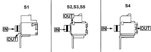
Vehicle speed input and outut sensor (active sensors)
The output speed sensor measures the vehicle speed from the number of revolutions of the parking gear, whilst the input speed sensor measures the input speed in the automatic transmission from the number of revolutions of the drum C1: both then send a signal to the automatic transmission control unit.
Active sensor specifications:
- the sensor has a Hall integrated circuit which manages the rectangular wave signal producing energy and transmits the signal to the automatic transmission control unit making use of the Hall effect. The automatic transmission control unit recognizes the signal in relation to the speed of the vehicle. The specifications of the output signal are fixed and do not depend on the number of revs.
- strong signal for noise
- a low number of revs may also be measured (10 rpm).
Specifications of impulse sensors:
- in relation to the speed of the vehicle, as a result of the rotation of the gear, an induction electromotive force sinusoidal wave is created which is then transmitted to the automatic transmission control unit. The control unit converts the wave signal into an impulse signal and recognizes it in relation to the speed of the vehicle. The specifications of the output signal depend on the number of revs
- the minimum number of revs that can be detected is 50 rpm.
Fluid temperature sensor
The fluid temperature sensor is fitted directly on the valve body which converts the temperature of the fluid inside the automatic transmission into an electrical signal which is then transmitted to the automatic transmission control unit.
Linear pressure control solenoid (slt)
The linear pressure solenoid controls the throttle valve by means of a signal arriving from the automatic transmission control unit as well as the linear pressure of the clutch and the brake to reduce the shock from the gear change.Direct control
Lock-up clutch control solenoid (slu)
The lock-up clutch control solenoid controls the linear pressure of the lock-up clutch by means of the signal arriving from the automatic transmission control unit as well as the hydraulic pressure of the lock-up clutch to reduce the shock from the gear change.Direct control:
- Engine brake: Brake B3
- Neutral control (N): Brake B2

Gearbox pressure control solenoid (sls)
The gearbox pressure control solenoid carries out its function by means of a signal arriving from the automatic transmission control unit.Direct control:
- control of 2nd , 3rd , 4th speeds and neutral (N): brake B1
- control of 5th speed and reverse: clutch C2

Transmission drive
The switch and sensor assembly, fitted on the automatic transmission, connects the neutral starting switch, solenoids S1, S2, S3, S4, S5, SLT, SLU, SLS, the input speed sensor and the fluid temperature sensor with three terminals.Automatic transmission control unit pin out| A1 | Key lock solenoid (gear control assembly) |
|---|---|
| A2 | Gearbox lock solenoid (gear control assembly) |
| A3 | I.E. |
| A4 | I.E. |
| A5 | Open |
| A6 | Left door open signal |
| A7 | Open |
| A8 | Panel warning light signal |
| A9 | Panel warning light signal (gear control assembly) |
| A10 | Open |
| A11 | Signal from diagnostic line (K line) |
| A12 | A.B.S. |
| A13 | A.B.S. |
| A14 | Earth |
| A15 | Open |
| A16 | Open |
| A17 | Open |
| A18 | Open |
| A19 | Open |
| A20 | Open |
| B1 | Linear solenoid no. 5 |
| B2 | Output speed sensor (+) |
| B3 | Input speed sensor (+) |
| B4 | Automatic transmission solenoid valve unit signal |
| B5 | Throttle valve linear solenoid (+) |
| B6 | Throttle linear solenoid |
| B7 | Battery positive |
| B8 | Throttle valve linear solenoid (-) |
| B9 | Output speed sensor (-) |
| B10 | Input speed sensor (-) |
| B11 | Automatic transmission solenoid valv assembly signal |
| B12 | Automatic transmission solenoid valv assembly signal |
| B13 | Gear control unit signal |
| B14 | Gear control unit signal |
| B15 | Lock-up clutch linear solenoid (-) |
| B16 | Gearbox solenoid no. 2 |
| B17 | Gearbox solenoid no. 1 |
| B18 | Fuel system |
| B19 | Fuel system |
| B20 | Throttle linear solenoid |
| B21 | Fluid temperature sensor (+) |
| B22 | Fluid temperature sensor (-) |
| B23 | Automatic transmission solenoid valve unit signal |
| B24 | Gear control unit signal |
| B25 | Gearbox solenoid no. 4 |
| B26 | Gearbox solenoid no. 3 |
| B27 | Lock-up clutch linear solenoid |
| B28 | Earth (-) |
Automatic transmission control unit control functions
Control of gear change and lock-up clutch Depending on the gear change programmed, the control unit sends a signal to the solenoids S1, S2, S3, S4 and S5, which are in the on/off positions, to control the gear change in relation to the speed of the vehicle and the opening of the throttle valve.The 55-50 SN version does not h| ... DATA ERROR - CROPPED TEXT | Ошибка данных - Текст обрезан ... |
|---|