184000261 - INTRODUCTION - TIMING SYSTEM
SPECIFICATIONS
Two cast iron camshafts, in a camshaft housing; driven by a belt and sprockets.COMPOSITION
There are the same number of suitably positioned cams as there are valves to operate.At the front, the exhaust shaft is prepared for the fitting of the toothed pulley, through which the movement of the crankshaft is received, by means of a suitably tensioned belt. (see 'Repair Procedures').A pair of gears, fitted at the rear of the shafts, allows the transfer of the power from the exhaust shaft to the inlet shaft.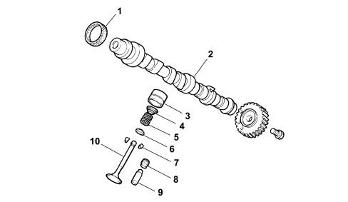
HYDRAULIC TAPPETS
The hydraulic tappets, fitted on this version, automatically cancel the valve clearance during engine operation, with the advantage of reducing:
- maintenance operations
- engine noise.
Operation in open stage
When the camshaft cam acts on the cup (1) and consequently the piston (2), the oil trapped in the chamber (6), because the ball valve (4) closes, transmits the movement of the piston (2) directly to the sleeve (3) and so to the valve. During this stage, because of the high pressure to which it is subjected, some of the oil in the chamber (6) leaks through the tiny gap between the piston (2) and sleeve (3).
Operation in closed stage
While the valve is closed, so that the tappet, pushed by the action of the spring (5), follows the profile of the cam, a vacuum is created inside the chamber (6) which causes the ball valve (4) to open, allowing oil to enter. The oil entering the chamber (6) replaces the oil which leaked out previously while the valve was open.