184000327 - INTRODUCTION - A(B.S. ANTI-LOCK BRAKING SYSTEM .)
CONSTRUCTION FEATURES
The vehicle is fitted with an ABS/EBD brake control system.The ABS/EBD system is Bosch 8.0, developed from the ABS system formerly fitted to other cars.The ABS is fitted in parallel to the hydraulic brake system so that braking is still assured even if the ABS is faulty.The ABS incorporates EBD (Electronic Brakeforce Distribution) to regulate and distribute brakeforce electronically over the axles. The brake system does not therefore include a mechanical load proportioning valve to distribute weight over both axles.GENERAL VIEW
SPECIFICATIONS
The Bosch 8.0 ABS control unit is an advanced version connected to the C-CAN network. It takes the name of NFR (brake node) and comes in 3 versions:
- With EBD
- With EBD and EPS system (Electronic Stability Program) that includes ASR/MSR/HBA/HHC functions.
COMPOSITION
Structure
The Bosch 8.0 A.B.S. system consists of:
- an electronic control unit built into the hydraulic control unit;
- an electro-hydraulic control unit which modulates the braking pressure via eight solenoid valves, two for each wheel;
- four ACTIVE MAGNETORESISTIVE sensors which detect the angular rotation speed of the wheels.
- wiring with specific connector.
OPERATION
Introduction
The electronic control unit processes signals from active sensor and the brake light control switch. The control unit then implements strategies to detect the wheel or wheels that are tending to lock (maximum slip between wheel and road surface). The unit then modulates brake fluid pressure selectively for the front wheels and in tandem for the rear wheels (select-low function).The ABS system modulates braking pressure in three basic stages:
- 1st pressure maintenance stage;
- 2nd pressure reduction stage;
- 3rd pressure increase stage.
Operating strategies
Pressure increase stage without abs intervention
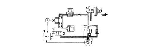
With the brake pedal pressure, the electronic control unit (1):
- does not supply the pressurizing solenoid valve (N.A.) (2)
- does not supply the discharge solenoid valve (N.C.) (3).

Situation with abs intervention
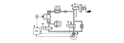
Pressure maintenance stageThe electronic control unit (1):
- supplies the pressurizing solenoid valve (N.A.) (2)
- does not supply the discharge solenoid valve (N.C.).
The electronic control unit:
- supplies the pressurizing solenoid valve (N.A.) (2)
- supplies the discharge solenoid valve (N.C.) (3).

The electronic control unit (1):
- does not supply the pressurizing solenoid valve (N.A.) (2)
- does not supply the discharge solenoid valve (N.C.) (3).
Ebd function (electronic brake force distribution)
The EBD function controls the distribution of the brake force and therefore replaces the conventional mechanical load proportioning valve making it possible to:
- act only on the rear brakes;
- improve the distribution of the brake forces
- intervene in an optimum manner in all load conditions (static or dynamic), driving conditions (in a straight line or round bends) and condition of the vehicle (tyres, brakes and suspension worn);
- implement a strategy which follows the ideal distribution curve.

A failure in the EBD function is signalled by the following warning lights coming on simultaneously:
- ABS warning light;
- insufficient brake fluid and/or handbrake applied warning light.
Recovery
The electronic control unit is equipped with a safety circuit which has the task of safeguarding the efficiency of the ABS system.With the ignition key inserted, the safety circuit checks the following for 4 seconds:
- the operation of the electronic control unit
- it activates the solenoid valves to check their operation
- checks the C-CAN network
With the vehicle driving, the safety circuit behaves in the following way:
- it continuously compares the angular speed of the wheels with the reference speed calculated
- it checks the memory conditions
- it checks the operation of the solenoid valves and the pump motor
- it constantly checks the battery voltage
- monitors efficiency of the C-CAN
If the safety circuit has detected one or more irregularities with the system components during the checking stage it behaves in the following way:
- it switches off the ABS system while still ensuring the efficiency of the conventional braking system
- it signals the irregular condition to the driver by the warning light in the instrument panel coming on.