184000328 - 3340A ABS CHECK/ADJUSTMENT DEVICES
COMPONENT DESCRIPTION
Electrohydraulic unit
Composition
StructureThis consists of an electronic cotnrol unit (1) and an electro-hydraulic control unit (2).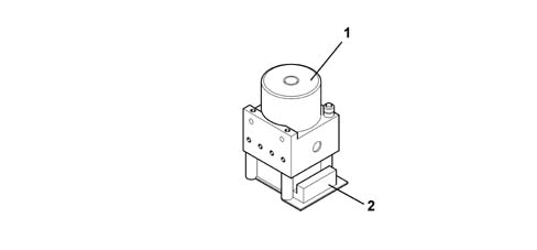
Electronic control unit
Specifications
OperationThe electronic control unit performs the following functions:
- downloading data from the wheel rpm sensors
- memorizing the control parameters defined during the preparation of the vehicle
- memorizing the control software
- processing the data acquired
- controlling the braking process
- detecting ABS component faults
- memorizing fault codes and activating the ABS and EBD warning lights
- sending and receiving data via the C-CAN line
- sending and receiving data via the diagnostic connector.

Hydraulic control unit
Specifications
OperationResponsible for modulating the pressure of the fluid at the brake calipers via two solenoid valves with the following stages:
- brake fluid pressure increase
- brake fluid pressure maintenance
- brake fluid pressure discharge.
Composition
StructureThe electro-hydraulic control unit consists of:
- eight two-way solenoid valves
- a dual circuit electric recovery pump
- two low pressure accumulators
- two high pressure accumulators

Active sensors
Specifications
Features of the systemThe adoption of active sensors offers the following advantages:
- less sensitivity to the distance between the sensor and the magnetic ring (gap)
- it reduces sensitivity to electro-magnetic interference
- the active sensor is able to measure wheel rpm speeds down to zero (instead of 2.5 km/h with the passive sensor)
- it produces savings in weight and size
- it simplifies the transmission couplings through the elimination of the phonic wheels.
Composition
StructureThe active sensors consist of two basic parts:
- a magnetic multi-polar codifier (1) integrated in the instrumented wheel hub bearing
- a 'magnetic-resistive' receiver (2) opposite the codifier.

Operation
Introduction
The operation of the sensor is based on the variation in the internal electrical resistance depending on the intensity and the direction of the lines of force of an external magnetic field (multipolar magnetic codifier) producing a variable square wave signal whose frequency depends on the rotation speed of the wheel, but whose range is constant.The active sensor is thus a proximity sensor with its own electronic system. It is connected to the ABS control unit by means of an electrical supply cable and sends vehicle speed information to the control unit.The phonic ring is a multipolar ring, an elastomer with a certain quantity of magnetic particles which are aligned by means of a special magnetization technique to produce different magnets with alternating north and south polarity around the circumference of the ring.