184000365 - INTRODUCTION - EXTERIOR LIGHTING
LOCATION OF COMPONENTS ON VEHICLE
The vehicle components and their location are illustrated below.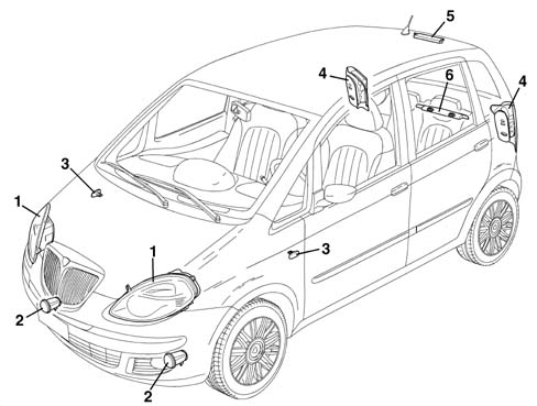
COMPOSITION
The vehicle exterior lighting system has been designed and produced with two objectives in mind:
- guaranteeing maximum efficiency with regard to the international regulations that define the lighting technology specifications for the various components;
- being integrated with the design of the vehicle so that the various components enhance the image.
FRONT LIGHT CLUSTER
The unit consists of: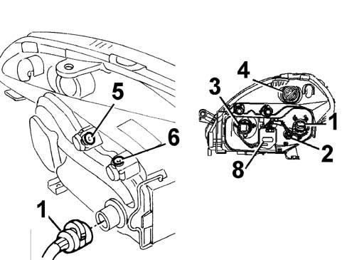
- Bulbs present:
- H7LL halogen bulb for dipped headlights function 12V-55W
- H3 halogen bulb for main beam headlights function 12V-55W
- All glass W5W bulb for side lights function 12V-5W
- P21W orange bulb for direction indicators function 12V-21W
Connector pin out
The connector pin out is illustrated in the diagram.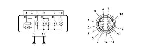
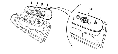
REAR LIGHT CLUSTER
The light cluster carries out the following lighting functions:
- Side light
- Brake light
- Reversing light
- Direction indicator
- Rear fog lamp
Bulbs present:
- P21/5W double filament bulb for side/brake lights function 12V- 5W /21W
- P21W bulb for reversing lights function 12V- 21W
- PY21W bulb with orange lens cover for direction indicators function 12V - 21W
- P21W bulb for rear fog lamps function 12V- 21W
Connector pin out
The connector pin out is illustrated in the diagram.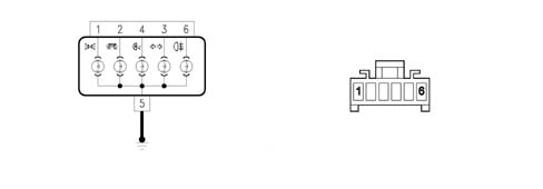
DIRECTION INDICATORS SIDE REPEATER
The side repeater is illustrated below.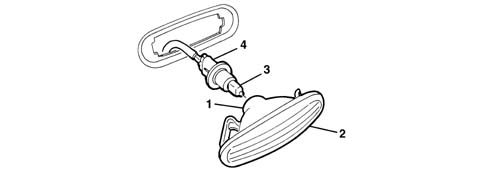
NUMBER PLATE LIGHT
The number plate light is illustrated below.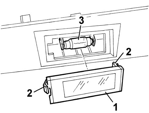
ADDITIONAL BRAKE LIGHT
The additional brake light function is achieved by means of a multi-bulb light fitted on the top part of the tailgate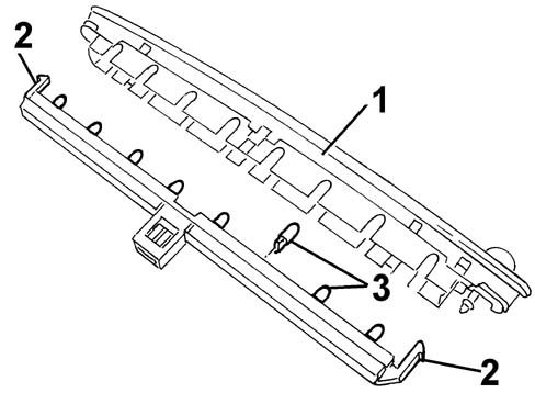
FOG LIGHT
The fog lights are located in the lower part of the front bumper. The unit has a screw for adjusting the direction of the light beam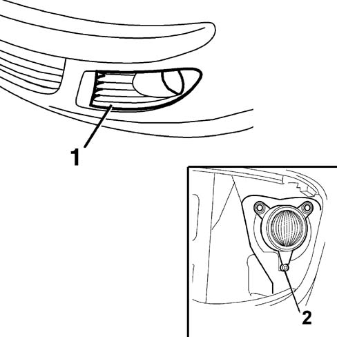
LIGHTS OPERATION
SIDE LIGHTS AND NUMBER PLATE LIGHT
The side lights come on when the ring nut on the steering column switch unit left lever is turned to the first position. Characteristic of working principle 5050 SCREEN WASHERS AND HEADLAMP WASH/WIPEThe switching on of the side lights is managed by the Body Computer: the side lights control function is activated through the enablement signals with the key in the ON position and the command from the steering column switch unit. Activation/deactivation information is sent via the CAN network: in this way, the side lights warning light in the instrument panel is also activated. The instrument panel also activates the nightime lighting.The "parking lights" function is turned on - only with the ignition OFF - by pressing the button in the panel to the left of the steering wheel: engagement is signalled by a roger beep. If the steering column switch unit left lever is turned (in the same way as for activating the direction indicators) it is possible to choose whether to turn on the side lights on both sides of the vehicle (lever in middle position) or only those on one side (lever downwards to select the left side, lever upwards to select the right side).Dusk sensor
The side lights and the dipped headlamps can be automatically activated using the dusk sensor if the AUTO function in the steering column switch unit is set.The dusk sensor is an infra red device which operates at different sensitivity levels: when the dusk sensor is activated a message is shown on the instrument panel display indicating the sensitivity setting (from 1 to 3): this intensity can be adjusted using the "Mode +" and "Mode -" buttons in the control panel to the left of the steering wheelLocationThe dusk sensor, integrated with the rain sensor, described below, is located on the windscreen, just below the rear view mirror.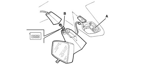
Follow me home
The "Follow me home" function allows the dipped headlamps and the side lights to remain on even after the engine has been switched off (key in OFF position) for a period of 30 seconds or multiples thereof. It is turned on using the lever in the same way as for activating the flasher within 2 minutes of the ignition being switched OFF: each time the lever is operated, the period for which the lights are on is increased by 30 seconds to a maximum of 210 seconds. The function is excluded if the ignition is turned ON or if the flasher lever is operated for more than 2 seconds.DIPPED BEAMS
The vehicle is equipped with two dipped beams in the headlamps.The dipped beams are activated by turning a wheel on the stalk switch to the next position after the side light setting.A special relay - managed by the Body Computer - controls the engagement of the dipped headlamps using the enablement signals with the ignition ON and the specific steering column switch unit command signal.With the dipped headlamps on, the simultaneous presence of the main beam and fog lights commands disables the dipped headlamps. The subsequent deactivation of one of these two commands, with the dipped headlamps control still on, means that the dipped headlamps will be turned back on again.MAIN BEAMS
The vehicle is equipped with two main in the headlamps.The main beams are switched on by the steering column switch unit:
- with the dipped beams on, by pushing the lever towards the dashboard (stable mode)
- in flashing mode, by pulling the lever toward the steering wheel (unstable mode)
| for legal reasons, if the dusk sensor is activated, only the flasher can be operated and the main beams cannot be turned on permanently; the AUTO function must be switched off in order to activate these lights. |
DIRECTION INDICATORS/HAZARD WARNING LIGHTS
The left and right direction indicators are switched on by raising or lowering the special lever on the left of the steering column switch unit; the function is activated with the ignition key in the ON position.The hazard warning lights (left and right direction indicators operated simultaneously) are activated via a button in the centre of the dashboard amongst the climate control system controls and all the direction indicators are activated at the same time. An LED at the back of the control button also comes on synchronized with the flashing of the exterior lights; this function is always activated.The engagement of the direction indicators / hazard warning lights is managed by the Body Computer which also controls the flashing frequency which is sent to the other nodes via the CAN serial network. In this way the two direction indicator warning lights in the instrument panel are also switched on; in addition, the system provides a low frequency acoustic signal in conjunction with the activation of the lights.BRAKE LIGHTS
The vehicle brake lights are located at the rear in the side light clusters and in the special central third brake light.They are operated each time the brake pedal is pressed via the special switch on the actual pedal.The switch fitted on the pedals consists of two contacts which supply two signals: the first is the N.A. type and recognizes the position of the brake pedal if it is not in the rest postion, i.e. the pedal is pressed; the second is the N.C. type and recognizes the position of the brake pedal in the rest position.The lights are turned on by the N.A. contact (pedal pressed). The N.A. switch information is sent, in particular, to the engine management control unit and to the ABS control unit, whilst the N.C. switch information aids the engine management control unti, especially for the Cruise Control function.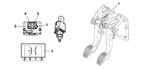
REVERSING LIGHTS
The vehicle has two reversing lights located in the rear light clusters, which are activated each time reverse gear is engaged via the special switch located on the outside of the gearbox casing.The signal that reverse gear has been engaged is managed by the Body Computer which forwards this information to the steering column switch unit as well for the automatic operation of the rearscreen wiper and to the parking sensors control unitFOG LIGHTS
The vehicle is equipped with two additional fog lamps located in the front bumper activated via the special button in the controls to the left of the steering wheel; when the lights are on, the warning light in the instrument panel comes on.A special relay - managed by the Body Computer - controls the engagement of the fog lights: relay excitation is activated with:
- enablement signal with key in ON position
- control signal coming from the switch
- side lights on signal.
REAR FOGLAMPS
The vehicle is equipped with two bright rear fog lamps located in the rear light clusters, activated via the special button in the controls to the left of the steering wheel; when the lights are on, the warning light in the instrument panel comes on.The switching on of the rear fog lamp is managed by the Body Computer: it is activated by:
- enablement signal with key in ON position (INT);
- control signal coming from the switch;
- dipped headlamps or fog lights on signal.
lights check
The correct operation of the following lights:
- side and number plate
| ... DATA ERROR - CROPPED TEXT | Ошибка данных - Текст обрезан ... |
|---|