184000369 - INTRODUCTION - ON BOARD INSTRUMENTS
INSTRUMENT PANEL NODE
SPECIFICATIONS
The panel is installed in the centre of the dashboard. Its position guarantees maximum visibility/legibility of the information for the driver in all vehicle usage conditions (day/night) without reflections, distortions or double images.Control Panel
View of assembly: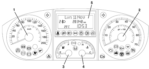
Composition
It is a TN (Negative Transmission) technology panel connected to the CAN and includes indicators with stepping motors for:
- Electronic speedometer
- Electronic rev counter
- Fuel level (with insufficient fuel level warning light)
- Engine coolant temperature gauge (with overheating warning light)
A buzzer offers the possibility of managing signals of different intensity for the following functions:
- Alarm/warning/danger signals;
- Button pressing roger beep.
The top line, with 14 dot matrix characters (7x5) is for displaying:
- Date
- Trip computer data
- Set-up menu with messages for settings/adjustments;
- Messages for activating functions, service, failure or warning;
The bottom two lines in segments are for displaying:
- Milometer;
- Clock;
- Outside temperature and "ice danger" symbol;
- Headlamp alignment corrector reading;
- "Return to workshop" symbol (spanner)
- City operation warning light
Dismantling
| The panel cannot be dismantled, it can only be removed from the vehicle and refitted. |
| Battery disconnection. If the power supply fails (vehicle battery disconnected), the instrument panel keeps the information received and should not be initialized. However, the trip mileage and clock data might be lost, whilst the personalization data and total mileage are preserved. When the power supply is restored, the indicators return to the start of the scale. |
| PANEL REPLACEMENT. Several of the CAN nodes, including the instrument panel, are programmed with default settings that the customer will find when they acquire the vehicle. If the panel is replaced, the Parts Dept. will send a "virgin" component. once fitted, the data memorized by the Body Computer must be transferred to it by carrying out the PROXI ALIGNMENT procedure using the Examiner. |
Warning lights in instrument panel
The warning lights in the instrument panel are illustrated below.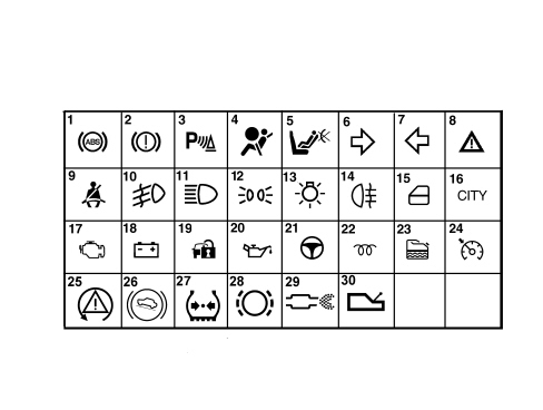
Rear view of instrument panel
The rear view of the instrument panel with the double connection is illustrated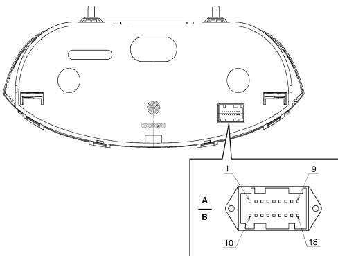
| Pin | Signal |
|---|---|
| 1 | Earth |
| 2 | Direct power supply |
| 3 | Ignition-operated power supply |
| 4 | N.C. |
| 5 | B - CAN A |
| 6 | B - CAN B |
| 7 | Headlamp alignment correction signal |
| 8 | Dipped headlamps signal for headlamp alignment corrector |
| 9 | Button signal for Trip Computer from steering column switch unit |
| 10 | N.C. |
| 11 | N.C. |
| 12 | N.C. |
| 13 | Mode and Mode + control signal from control panel |
| 14 | Headlamp alignment corrector signal from control panel |
| 15 | N.C. |
| 16 | Mode and Mode - control signal from control panel |
| 17 | N.C. |
| 18 | EOBD failure warning light |
OPERATION
Display at key on
At each key on the check on all the electronic control units present in the vehicle begins with several of the warning lights in the panel coming on; in addition the message "Check in progress" appears on the display.During the check stage, the following warning lights are checked at the key on:
- Fuel reserve
- Radiator coolant overheating
- Cruise control on
- ABS failure
- Insufficient brake fluid level
- Electric steering failure
- Diesel filter water

Set-up menu display
Access to the menu screenThe buttons for the set up are in the control panel to the left of the steering wheel in the dashboard: pressing MODE activates the MENU ambient. The "+" and "-" buttons are used to "navigate" inside the MENU, pressing MODE again confirms a selection. The items in the menu can be displayed in two ways at this point: with the vehicle moving and with the vehicle stationary.If no operation is carried out for a certain length of time, the standard screen is restored.Some of the set-up MENU functions can only be activated with the vehicle stationary: for safety reasons, with the vehicle moving, only a reduced set-up menu is available: selection of speed limit and dusk sensor sensitivityActivation/deactivation of automatic locking of 5 doors above 20 km/hActivation/deactivation of unlocking of (driver''s) front door onlyActivation/deactivation of boot release together with unlocking of all the doorsAdjustment of clock and 12h/24h modeAdjustment of the dateService interval display (km/miles/days)Speed: selection and setting of speed limit levelVolume of buzzer for alarms/failures/warningsSetting unit of measurement (distance, consumption, temperature)SettingDusk sensor sensitivity (where fitted)Trip "B''Button pressing buzzer volume (roger beep)Dimmer lightThe instrument allows the user to adjust the brightness of the display and the instrument panel as well as the controls for the radio, climate control etc. by pressing the "Mode +" and "Mode -" buttons.The adjustment of the brightness is also shown on the display by the "Lighting" message and the brightness adjustment symbols switching on/off. .
Rev counter
The control and operating electronics use a microprocessor with the engine rpm reading produced using a stepping motor guaranteeing precision and continuity throughout the entire scale and a reading in extreme operating conditions.At the key on the indicator is at 0 (zero) RPM and the instrument panel receives the engine rpm information.Milometer
When starting, the milometer display shows the total or trip mileage in km (or miles) memorized until the previous key off.The trip meter is zeroed by keeping the SET button in the steering column switch unit pressed for longer than 2 secs. - The distance unit of measurement (km or miles) can be changed using the menu in the instrument panel.The display is interrupted at the key off, except when the front doors are opened/closed.Zeroing the total mileageThe total mileage can only be zeroed once, within the first 200 km, after moving to Production or before delivery to the Customer.In the case of a new instrument the mileage reading is preceeded by an "H" (e.g. "H00199"). When 200 km is exceeded, the letter H automatically disappears and the reading becomes "000201".The equipment can be zeroed even if the steering column switch unit SET button is pressed, before the first 200 km, until the letter H disappears and the counting starts again from "000000".| This operation can only be carried out once |
Fuel level gauge
The control and operating electronics use a microprocessore; the fuel level reading is analogue produced using a stepping motorThe fuel level is measured by means of a sensor in the tank and is processed by a microprocessor interface which notifies the Body Computer and converts it into a tank percentage value.The circuit is capable of detecting a fault in the wiring or in the sensor and providing the instrument panel with a suitable reading (via the CAN).The system checks for the presence of a system malfunction and activates a fault signalling procedure: the pointer is at the start of the scale and the reserve warning light flashes.The system guarantees there are no fuel level fluctuations/incorrect readings due to the fuel splashing around in the tank.The switching on/off of the fuel reserve warning light in the instrument panel is also controlled by the Body Computer: the reading at the start of the "fuel reserve" is red and the warning light is produced by the amber LED in the indicator graphics.The fuel reserve condition is also signalled by means of a buzzer.Engine coolant temperature gauge
The engine coolant temperature control electronics use a microprocessor with the reading (which is activated at the key on) produced precisely by a stepping motor with the corresponding red coloured "danger zone".The temperature reading is always guaranteed, even in extreme operating conditions.At every key on the engine coolant overheating warning is checked by a continuous control signal via the dedicated red warning light.At temperatures of around 120 °C the coolant overheating warning light lights up and, at the same time, the pointer is positioned at the end of the scale.If there is a fault with the engine coolant temperature sensor, the instrument panel places the pointer in the rest position at the key off.Trip computer
The Trip Computer makes it possible to show measurements relating to the journey in the panel display, measured by means of a distance sensor.The Trip Computer information is transmitted via the CAN.The measurements displayed can be expressed according to the Decimal Metric System or the Imperial System, as selected by the driver (set-up menu).The Trip Computer information can be zeroed manually by the use by pressing the SET button for a long time.There are 2 types of TRIP:
- GENERAL TRIP (always activated)
- TRIP B (that can be activated/deactivated using the menu)
The data display mode follows a pre-set order: (GENERAL TRIP):
- Distance travelled [km] or [miles]: indicates the distance travelled by the vehicle from the "start of the journey", i.e. when the driver reset the equipment. The reading is consistent with the display on the total mileage recorder. The display is updated every 0.1 km
- Instant consumption [l/100 km] or [mpg]: indicates the litres of fuel consumed for the distance travelled. This makes the driver aware of differences in fuel consumption linked to driving styles.
- Average consumption [l/100 km] or [mpg]: this is the ratio between the distance travelled from the start of the journey (Distance travelled) and the number of litres consumed since the start of the journey. The display is updated every 10 seconds.
- Range [km] or [miles]: this indicates the estimated distance that can be travelled with the fuel currently in the tank based on the same style of driving being maintained.
| When the calculated "Range" value is the same as the fuel reserve, the display indicates "Limited Range" and a buzzer sounds. |

| ... DATA ERROR - CROPPED TEXT | Ошибка данных - Текст обрезан ... |
|---|