184000304 - INTRODUCTION - CLUTCH
CONSTRUCTION FEATURES
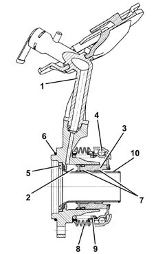
The clutch is the dry, single plate type with a thrust bearing always in contact with the flexible coupling spring.The driven plate is drven by pressure exerted by a diaphram spring. The clutch release is activated through the hydrauilc system operated by the pedal.COMPOSITION
The system consists of:
- a clutch pump (master cylinder) (2), which has the task of compressing the fluid and is fixed to the pedals;
- a connecting pipe (3) between the pump and the clutch operating cylinder;
- a clutch operating cylinder (4) fixed to the gearbox;
- linkage (5) operating the thrust bearing;
- a thrust bearing (6);
- a clutch drip tray with diaphragm springs (7);
- a clutch plate (8);
- a fluid reservoir (1) shared with the braking system.
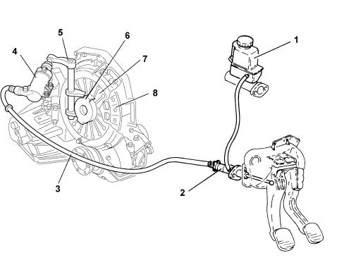
OPERATION
The pump (2), operated by the clutch pedal, pressurizes the hydraulic circuit and activates the clutch operating cylinder (4).The latter acts on the operating linkage (5), which 'pulls' the thrust bearing (3), overcoming the action of the pressure plate springs (7).This action uncouples the clutch plate (8) from the flywheel.When the pedal is released, the action of the diaphragm springs (7) returns the mechanism to the original position. For the 1.9 Multijet version, the clutch release system is under coaxial hydraulic control.With this type of control, there is no clutch release shaft, relevant bushes, external clutch release lever and the clutch cylinder (actuator).The system is defined as co-axial because the release actuator consists of an aluminium ring cylinder fitted inside the bell housing between the gearbox and the clutch mechanisms in a position which is co-axial in relation to the main shaft.The advantage of the system compared with traditional systems is that there are no kinematic couplings which results in improved reliability and functionality and make the system easy to maintain. The system has the following features:
- constant adjustment of the clutch pedal height;
- effort applied to the pedal constant over a period of time;
- elimination of clutch pedal return difficulties;
- reduction in the noise and vibrations from the pedal through the action of a damper on the cylinder fluid pipe.