2888242 - 1060F injectors and lines
INJECTOR
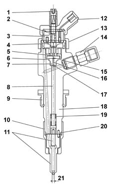
Construction features
Electromagnetically-controlled fuel
injector divided into 2 parts:
- solenoid consisting of coils and drive valves
- actuator/nozzle consisting of a pressure rod, pin, 5-hole
jet supplied at high pressure (up to 1300 bar with atmospheric pressure
recirculation)
1, Pressure rod
2, Pin
3, Jet
4, Coil
5, Valve
6, Spherical shutter
7, Control area
8, Supply volume
9, Control volume
10, Fuel return - low pressure
11, Control duct
12, Supply duct
13, Electrical connection
14, Fuel inlet connector - high pressure
15, SpringOperation
The electromagnetically-controlled UNIJET
fuel injector comprises a high-pressure supply duct and a recirculation
pipe at ambient pressure.The supply duct is connected to the rail
by a pipe which can withstand the high operating pressures; the
recirculation is sent to the tank.The chamber inside the pilot valve and immediately
above the actuator is called "control chamber", and it
of fundamental importance for the operation of the fuel injector. Control chamber
The control chamber is a small chamber permanently
supplied with line diesel through hole Z (from the German Zufluss
= inlet).The discharge from this chamber is through
A (from the German Ablfuss = outlet), the opening of which is controlled
by the control solenoid.The diesel contained in the control chamber
acts, at the supply pressure, on the upper surface of the pressure
rod, with area Ac; the force Fc which acts on this area thus depends
on the pressure Pc present in the control chamber. Solenoid control valve
The control solenoid controls the pressure
in the control chamber and so determines the instant when the actuator
allows introduction of fuel to commence, and the duration of introduction. The pressure in the control chamber is determined
by the opening and closure of hole A, effected by a spherical shutter
which is controlled by a pilot needle ("anchor").The pilot needle is normally held in the
closed position by a spring.When the electromagnet is energized, the
force of the spring is overcome and the pilot needle rises, allowing
the spherical shutter to uncover the hole A; the lifting of the
pilot needle is limited by a stop which is adjustable by an adjustment
screw. The nozzle is supplied with diesel under
pressure when the pressure rod-pin assembly is in the raised position.The pressure rod-pin assembly is
subject to:
- a) the elastic force Fe in the direction of closure, generated
by the spring which acts on the pin; this force ensures that the nozzle
seals when the line pressure falls to zero, preventing fuel from
dripping into the cylinder;
- b) the pressure Pc of the diesel (present in the control
chamber), which acts on the upper area of the pressure rod Ac; this pressure
Pc generates a force Fc, which also acts in the direction of closure;
- c) the pressure Pa of the diesel present in the supply
chamber; this acts on the area Aa of the circular ring which is
delimited on the outside by the diameter through which the pin slides
in the nozzle, and on the inside by the diameter of the sealing
edge of the conical seat. This pressure Pa generates a force Fa,
in the direction of opening.
Injector rest position
In the rest condition, the electro-magnet
is de-energized and the pilot needle is in the closed position.In the control chamber supplied by the hole
Z, the pressure Pc is equal to the line pressure, and so the forces
which act in the direction of closure of the pressure rod-pintle
assembly (Fc+Fe) prevail over the opening force (Fa). Under these conditions, fuel is not inserted
into the cylinder.1, Electro-magnet
2. Two-way valve
3, Nozzle
4, High pressure diesel inletStart of injection
When the electromagnet is energized, the
pilot needle rises and the hole A, whose discharge cross-section
is greater than that of the hole Z, is uncovered. Consequently the
diesel present in the control chamber is discharged, as a sufficient
amount is not supplied through the hole Z, and the pressure Pc decreases. The force Fc on the upper area of the pressure
rod decreases and, when the opening force Fa becomes greater than
Fc+Fe, the nozzle begins to open.From the supply chamber, constantly refilled
by the line pressure Pa, diesel begins to flow through the nozzle
and the introduction of fuel into the cylinder commences.1, Low pressure diesel recirculation
2, Electrical operation
3, High pressure diesel inlet
4, Flow hole open
5, Nozzle
6, Two-way valve
7, Electro-magnetEnd of injection
The de-energizating of the electromagnet
causes the hole A to close, which in turn causes the rapid increase
in pressure in the control chamber to the original value, resulting
in the re-balancing of the forces acting on the pressure rod-pin. As a result of the re-balancing of the forces,
the pressure rod and pin re-descend, stopping the influx of fuel
to the nozzle and so ending injection.For a better understanding of the stages
described, refer to the following diagram:1, Current
2, Pilot needle lift
3, Needle lifta) A current is applied to the ends of the
solenoid coil. This current is maintained for a time ET (Energizing
Time), depending on the quantity of fuel to be injected and the
supply pressure. b) The movement of the soleniod valve pilot
needle starts with a delay TRE (Energizing Delay Time) and the
control chamber begins to empty.c) The pilot needle homes at the top after
a time TRAA (Pilot Needle Opening Delay Time), depending on the
maximum lift, adjustable by means of a specific adjustment screw. d) After a time TRAS (Pintle Opening Delay
Time) from the start of the pilot needle's movement, the pressure
rod-pin assembly starts its movement and at the same time injection
commences; the time elapsing from the start of energization of the
electromagnet is called TRII (Start-of-Injection Delay Time). e) When the command to the electromagnet
stops, the pilot needle starts its descent travel, which ends after
a time TRCA (Pilot Needle Closure Delay Time), always dependent
on the maximum lift permitted by the needle; when the pilot needle descends,
the hole A closes and the control chamber fills up again. f) When the pressures are re-balanced, the
pressure rod-pin assembly re-descends, ending fuel injection. The
following times may be distinguished: TRCS (Pintle Closing Delay
Time), equal to the time elapsing between the closure of hole A
and the end of injection; TAS (Pintle Opening Time), equal to the
actual duration of injection, and TRFI (End-of-Injection Delay Time),
calculated from the end of the electrical command. Observations on the quantity introduced and the injection
advance
The quantity of fuel introduced at each
injection basically depends on two parameters: the duration of opening
of the pintle and the pressure in the supply chamber.As an initial approximation, it may be considered
that the pressure in the supply chamber is equal to the line pressure; however,
during injection, there is a slight reduction in pressure caused
by the injection itself. Since it is not possible to check and measure
the pressure in the supply chamber, because of difficulties of access
and the brevity of the time available, the injection pressure is
assumed to be the pressure measured in the rail. The length of the pintle opening depends
on the duration of the electrical command ET (Energizing Time);
in effect, the longer the duration of the electrical command, the
longer the pilot needle remains in the open position and the longer
the opening of the pintle. The actual duration of injection cannot
be immediately correlated to the duration of the electrical command
(later, when reference is made to the duration of injection, the
duration of the electrical command, or ET - Energizing Time - will
be considered), and in general the actual duration of injection
is greater than the duration of the electrical command, as the End-of-Injection
Delay Time (TRFI) is greater that the Start-of-Injection Delay Time
(TRII). The delay between the start of the electrical
command and actual injection (TRII) must be taken into account when
considering the actual injection advance; in fact, for the injection
advance, the UNIJET control system refers to the electrical command
and not the actual start of injection.The same considerations apply to the actual
end of injection, whose delay from the end of the electrical command
TRFI is greater than the start-of-fuel injection delay TRII.TRII and TRFI can be determined by appropriate
tests conducted on an injector test stand. In conclusion, to know the quantity of air
introduced at each injection, a test must be conducted to determine
the "measured injector plan", i.e. the characteristic
amount introduced in relation to ET at different injection pressures.


