2892439 - Introduction - BRAKING SYSTEM
CONSTRUCTION FEATURES
The vehicle is fitted with self-ventilated front disc brakes with floating calipers and rear drum brakes with self-centring shoes and automatic recovery of the clearance. The braking system is operated by a pedal with a 9' vacuum brake servo and a 13/16' master cylinder. The hydraulic system is the split type with two independent crossover circuits with a load proportioning v alve on the rear brake circuit (versions without ABS).1, Brake fluid reservor and pump for independent brake circuits
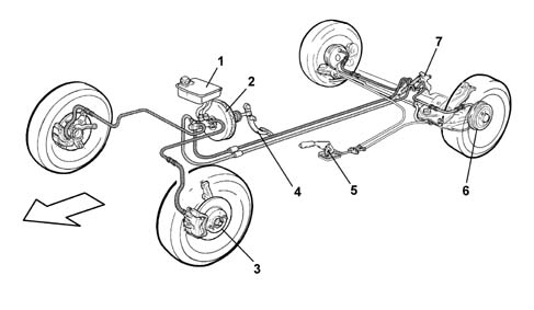
2, Vacuum brake servo
3, Front disc brakes
4, Brake pedal
5, Parking brake control lever
6, Rear drum brakes
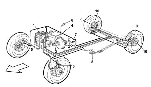
7, Load proportioning valveBosch A.B.S. 5.3 anti-lock brakes
with four active sensors and four channels are available on request.The system control unit controls the EBD
(Electronic Brake force Distribution) function for distributing
the braking between the front and rear axles (in this case a conventional
load proportioning valve is not fitted).Mechanical type handbrake with twin cable.
1, Electro-hydraulic control unit
2, Master cylinder
3, Brake servo
4, Brake fluid reservoir
5, Front rpm sensor
6, System failure warning light
7, Brake lights switch
8, Parking brake lever
9, Rear rpm sensor
10, Rear drums
CONSTRUCTION FEATURES
Versions equipped with rear disc brakes feature new brake calipers.These devices differ from similar systems used on other Group vehicles through the pad wear recovery system and consequently the adjustment.In particular, the direction of rotation of the cylinder whilst replacing the brake pads is always the same as the direction of rotation of the wheels during normal driving.On the left wheels the cylinder therefore rotates in an anti-clockwise direction and on the right wheels in a clockwise direction.The diagram below shows a cross section of the brake calipers.1, Handbrake idler lever
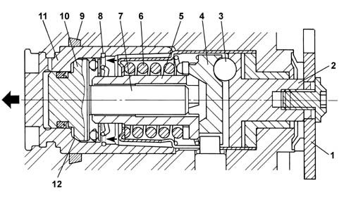
2, Drive transformation device active element
3, Ball
4, Drive transformation device passive element
5, Female screw
6, Reaction spring
7, Worm screw
8, Axial bearing
9, Seal in operating cylinder housing
10, Worm screw head
11, Operating cylinder
12, Clutch surfaces.The caliper features an irreversible type
worm screw, in other words it is capable of transforming axial motion
into rotary motion in one direction only and not in the other direction.In this way the operating cylinder can only
come out of the caliper casing and not go back into it.This device comprises a female screw (5)
and a worm screw (7).The female screw (5) forms one piece with
the fixed section of the caliper and is kept in contact with the
passive element of the drive transformation device (4) by the reaction
spring (6).The screw (7) forms one piece with the head
(10) and can therefore move together with the latter whilst the
cylinder is moving.When the operating cylinder (11) moves axially
in the direction shown by the arrow, it acts on the brake pads:
either as a result of the activation of the handbrake or following
the action of the oil on the inner surface of the head (10) during
the normal braking stage.If the handbrake is activated, the rotation
of the lever (1) causes the rotation of the active element of the
drive transformation device (2).Thanks to the presence of three balls (3)
on the same number of tilted planes, the rotary motion is transformed
into a movement that moves the passive element of the drive transformation
device (4).Given the connection between the passive
element (4) and the female screw (5), the latter also moves causing
the screw (7) and consequently the piston (11) to move forwards. During normal braking it is the pressure
of the oil acting on the inner face of the head that moves the actual
head and consequently the operating cylinder forwards until it is
in contact with the brake pads. It is obvious that when the pads are worn,
the movement of the cylinder is greater and under these circumstances
the screw (7) is loosened in relation to the female screw (5) by
a length equal to the wear of the actual pads.Whilst the brakes are released the screw
cannot tighten on the femal screw because the retraction of the
piston is limited, by the seal (9), to a few tenths of a millimeter,
absorbed by the operating clearance between the screw and the female
screw (about 0.5 mm); the recovery of the wear is therefore guaranteed
for subsequent braking.It becomes obvious that when a wear recovery
operation is required, there will be a rotary movment of the head
(10) in relation to the cylinder (11).This movement is impeded by the contact
surfaces (12) when the pressure on the inner face of the head is
greater than a pre-set limit of around 20 bar. At these pressure levels the dismantling
of the force derived from the action of the oil on the surfaces
(12) produces a friction that prevents rotation.The entire device therefore moves axially,
but without recovery.