2888255 - 1043A gpl tank (GPOWER)
CONSTRUCTION FEATURES
.
CONSTRUCTION FEATURES
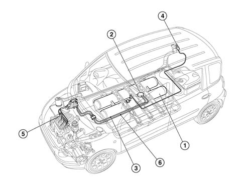
LPG (liquid petroleum gas) is stored in compressed form under pressure. The pressure ranges between a minimum of 1 and a maximum of 25 bars according to temperature and LPG composition. The gas container consists of a cylindrical tank (or two if requested as an option) that are filled through a special fitting connected to a rigid copper pipe connected to a valve that limits filling to 80%.A solenoid on the cylinder cuts off the LPG flow to the supply system when the system is switched from LPG to petrol supply or when the engine is shut down. The LPG is directed by a brushless a.c.submerged pump through a maintenance-free filter in the tank and a nylon fibre flexible pipe to a pressure regulation unit and then to injectors located directly on the intake manifold. A return line collects uninjected LPG and sends it to the tank. To ensure a constant pressure to the injectors and proper return flow of excess gas, the regulator ensures a pressure greater than 5 bars compared to tank pressure.LPG FILLER FITTING
The LPG filler fitting (2) is located next to the fuel filler (1).It includes a check valve (4) in the filler casing (3) connected to the LPG tank by means of a rigid copper pipe (5) with tapered fittings (6).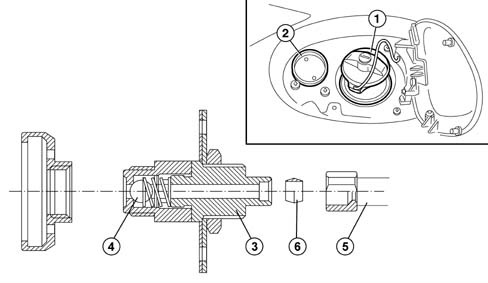
LPG TANK
Liquid LPG is stored at a pressure that ranges from 2 to 15 bars, according to temperature and LPG composition, in a cylindrical tank secured to the car floor. The canister is made entirely from steel (in accordance with regulations) and by law is subjected to a hydraulic test at a pressure of 30 bars for tank category A and exceeds the impact and crash test legal requirements (in accordance with ECE 1024 and ECE 34).| The LPG cylinders have been certified in accordance with EU regulations ECE R67/01. Cylinders last for 10 years; After this period they must be sent to the appropriate Centres for overhaul. |
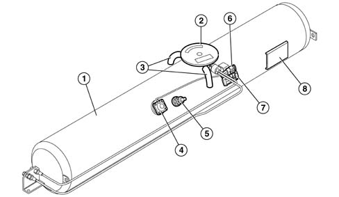
The tank weighs some 41 kg and is surface-treated to a thickness of 60 microns with corrosion-proofing products. It consists of:
- chamber (1) containing liquid gas (which may be doubled to increase tank capacity when a second tank is ordered as an option) that contains a submerged LPG feed pump;
- a sealed chamber with a cover (2) and two vent pipes (3) leading to the outside that contain delivery and return valves in addition to electronic components controlling the submerged pump;
- a liquid LPG level detection device connected to the gauge via the LPG control unit located inside a magnetic transducer (4);
- an LPG refuelling 80% valve (5);
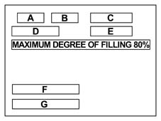
G. homologation codes
- for single tank:
E4 67R-010031 CLASS 1:
- for double tank
VALVE ASSEMBLY ON TANK
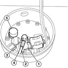
No maintenance work can be carried out on the valve assembly in the tank, commonly known as a 'valve unit'. With the exception of the uptake soleniod coil and the submerged pump electronic control unit, every other intervention must be carried out by the tank supplier. The valves are positioned in the tank in such a way as to allow part of them to be contained in a single chamber known as a sealed chamber. This is fitted with a cover (1) secured by a bolt (2) that separates it from the external environment. The lower part of the cover is fitted with electronic components (3) that control the submerged pump. Althoug the underlying chamber is said to be sealed, it communicates with the external environment through two pipes that allow ventilation of the area surrounding the valves as required by international legislation. In this way, gas build-up due to minor leaks from the valves is prevented.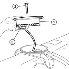
Unit components are listed at operational level:
- Normally-closed input solenoid (1) on the delivery pipe (2) that prevents LPG flowing from the cylinder to the engine when deactivated.
- One-way return valve (3) located near return pipe (4) from the pressure regulator valve. The function of the valve is to prevent LPG emerging frm the tank in the case of accidental pipe breakage. The valve also damps gurgling due to liquid falling into the tank.
- Mechanical valve commonly known as an 80% safety valve that cuts in during refuelling; when the volume occupied by the liquid gas inside the tank reaches 80% of total tank volume, the valve automatically blocks LPG refuelling.
| Faulty valve operation could bring about excessive valve filling with a consequent dangerous anomolous increase in internal pressure. |
| If anomalously excessive tank filling is detected upon refuelling with LPG (i.e. starting from a gas level reading of 0, exceeding the maximum permitted quantity of 50 litres of LPG for the single tank and 88 litres in the case of a double tank), replace the safety valve that limits the level of liquid in the cylinder (80% valve). Nominal tank capacity is 58 litres, corresponding to an effective capacity of 48+2 litres (rated capacity of the optional double tank is 112 litres, equal to an effective capcity of 86+2 litres). |