2888279 - 5040A air conditioner coolant circuit
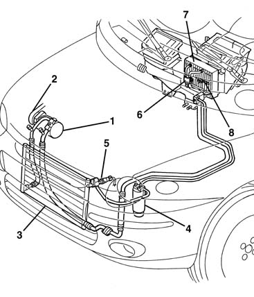
The air conditioning system is designed to cool and dehumidify the air to be introduced into the passenger compartment.Location of system components
-
Air conditioner compressor
Variable capacity compressors
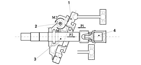
SpecificationsAll versions are fitted with a variable capacity compressor.This type of compressor has a special feature compared with traditional rotary type compressors; the electro-magnet coupling doe not have to be continuously switched on/off, with it consequently being subject to excessive stress, to allow the activation of the compressor.In effect, the latter, always rotating, modifies its intervention by varying the capacity according to the air conditioning required (temperature decrease) as illustrated below.The compressor varies its capacity following the variations in the system load conditions. - altered outside temperature and/or humidity conditions.This solution also makes it possible to improve the protection of the evaporator, reducing the intervention of the frost thermostat.OperationThe capacity is altered by changing the inclination of the connecting rod holder plate (1), achieved by varying the equilibrium of the presures and consequently the forces acting on the actual plate.This equilibrium is modified through the opening of the diaphragm valve (4) according to the following logic:
- when the inlet pressure is high, the valve (4) remains closed; the reaction forces of the pistons P1 mainly act on the hinged (2) plate (1) causing a clockwise movement M1 applied to the plate hinge, which remains in the maximum inclination position;
- if the inlet pressure falls, the difference in pressure downstream of the diaphragm opens the valve (4): this gives rise to a pressure thrust on the shaft (3) which results in P2 which causes an anti-clockwise movement M2 which tends to rotate the plate (1) towards a more vertical position, i.e. a gradual reduction in the displacement.
Compressor
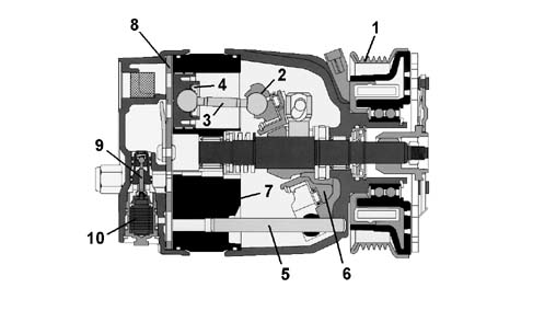
CompositionThe compressor fitted on this version is he DELPHI V5 variable capacity type, shown diagramatically in the inset in the diagram above and consists of:
- a cylinder block/crankcase (7) which contains the liners/bores in which the pistons (4) slide;
- an assembly consisting of a shaft on which an inclined plane (6) is fitted on which a disc (2) guided by a pin (5) fixed to the five connecting rods (3) which operate the pistons (4) rotates on roller bearings;
- a cylinder head which contains the inlet and supply manifolds in addition to the seat for the adjustment valve (9) ;
- a plate (8), positioned between the cylinder block/crankcase and the cylinder head, which contains the inlet and supply valves:
- a pulley assembly with an electro-magnet coupling (1)
Air conditioning condenser
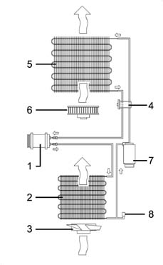
The condenser is a heat exchanger located in front of the engine cooling radiator.The refrigerant fluid, in a gaseous state, passes through the condenser coils and liquifies (at an average temperature of 60°C).The outside of the condenser comes into contact with the air produced by the vehicle moving forwards. When the vehicle is stationary or in a traffic jam, the air is produced by the same fan used by the engine radiator.An insufficient heat exchange in the condenser increases the pressure in the system and causes the incomplete condensation of the fluid with a considerable reduction in the efficiency of the system.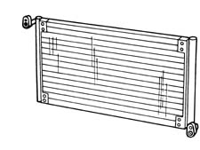
Drier filter
The drier filter is connected by a pipe to the evaporator inlet duct and filters the refrigerant fluid mainly in a gaseous state but partly also in a liquid state, plus the lubricant oil/anti-freeze.Any small impurities which could obstruct the expansion valve are retained by two filter layers whilst the (dehydration) water is retained by molecular sieves or a chemical compound (SILICAGEL) to prevent any particles of moisture contained in the system from freezing in the expansion valve and stopping it from working.For this reason all the system components must be stored in a dry place with the connectors sealed until the time of fitting.In the lower part of the pipe, which is positioned inside the accumulator and is contact with the outlet connector, there is an opening to ensure the return of the lubricant oil/anti-freeze to the compressor. There is a metal gauze filter seal on the above mentioned pipe, by the opening for the oil.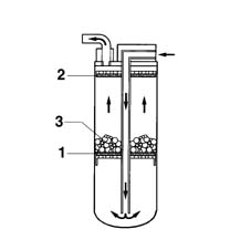
3 stage pressure switch
A three stage pressure switch controls the safe and correct operation of the circuit.The three pressure stages allow the compressor and the cooling fan to be switched on/off as follows:
- 1st level (below 2.5 bar approx): minimum pressure allowing the compressor to be switched on
- 2nd level (15 bar approx): pressure that requires the condenser cooling fan to be switched on
- 3rd level (beyond 28 bar approx): pressure too high and therefore dangerous for the entire system
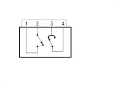
Wiring diagram
pins 3-4 1st and 3rd levelspins 1-2 2nd levelExpansion valve
The thermostatic expansion valve fitted on the evaporator inlet and outlet ducts has the task of regulating the flow and expasion (fall in pressure) of the R134a fluid before it enters the evaporator.The automatic regulation of the passage section for the refrigerant fluid inside the expansion valve is carried out by a sensitive bulb which, according to the temperature of fluid, suitably adjusts the size of the opening acting on a special spring which moves a shutter and determines the extent of the expansion.The increase in temperature at the evaporator outlet, measured by the sensitive bulb, causes the opening of the valve with a consequent increase in the flow rate of the fluid to the evaporator.Conversely, at low temperatures, the flow rate is decreased.The valve adjustment screw is calibrated in production and should not be tampered with: this would involve a decrease in the efficiency of the system.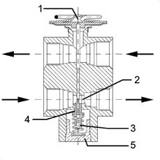
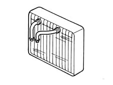
Evaporator unit
The evporator is the second heat exchanger in the system and consists of an aluminium structure with fins which increase the heat exchange surface. It is located in the duct/distributor unit.The evaporator inlet and outlet ducts are fixed to the assembly plates which constitute the heat exchange area. The evaporator is chemically treated to make it corrosion resistant.It represents the system cooling element and can have (recirculation) air coming from the passenger compartment or air from the outside passing through it for the necessary exchange of air inside the passenger compartment.The outside or recirculation air which passes through the evaporator is at a higher temperature than that of the refrigerant fluid, in a liquid tate at a low pressure and temperature, which it contains and this causes evaporation (always at low pressure).At the same time, the air which comes into contact with the evaporator fins is cooled and dehumidified. The humidity which condenses on the evaporator fins is collected and discharged outside the vehicle.