2892439 - Introduction - BRAKING SYSTEM
CONSTRUCTION FEATURES
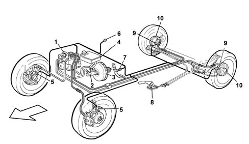
The vehicle is fitted with self-ventilated front disc brakes with floating calipers and rear drum brakes with self-centring shoes and automatic recovery of the clearance. The braking system is operated by a pedal with a 9' vacuum brake servo and a 13/16' master cylinder. The hydraulic system is the split type with two independent crossover circuits with a load proportioning v alve on the rear brake circuit (versions without ABS).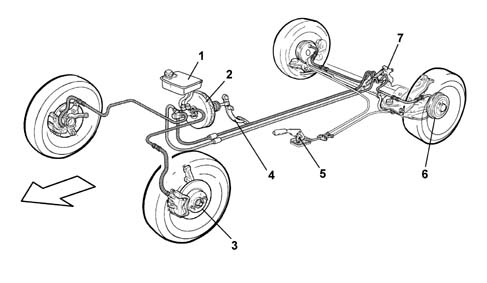
CONSTRUCTION FEATURES
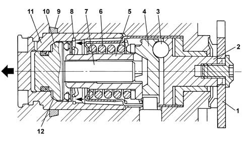
Versions equipped with rear disc brakes feature new brake calipers.These devices differ from similar systems used on other Group vehicles through the pad wear recovery system and consequently the adjustment.In particular, the direction of rotation of the cylinder whilst replacing the brake pads is always the same as the direction of rotation of the wheels during normal driving.On the left wheels the cylinder therefore rotates in an anti-clockwise direction and on the right wheels in a clockwise direction.The diagram below shows a cross section of the brake calipers.