3025236 - 3330D02 brake servo/brake pump assembly - r r
 | Name | Connector |
|---|---|---|
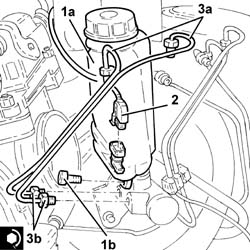
| 2 | Brake fluid level sensor (switch) | K25 |

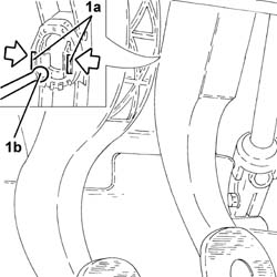
| Take care not to damage the retaining clips. |

 | Fastening | Component | Ø | Value(daNm) |
|---|---|---|---|---|
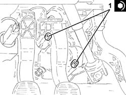
| 1 | Nut | BRAKE SERVO | M8 | 2.2 |
| Fastening | Component | Ø | Value(daNm) |
|---|---|---|---|---|
| 3b | Connector | PIPE FROM PUMP TO HYDRAULIC CONTROL UNIT | M12 | (Master cylinder side) 1.3 ÷ 1.5 |