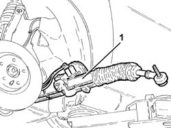
3025290 - 4130A10 power steering box - r+r - check tow-in if necessary separately - includes bleeding
| The bolt is pretreated and cannot therefore be refitted. |
 | Name | Country |
|---|---|---|
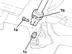
| 1c | Extractor | 1.821.169.000 |
| Name | Country |
|---|---|---|
| 1a | Flange | 1.860.978.000 |
 | Fastening | Component | Ø | Value(daNm) |
|---|---|---|---|---|
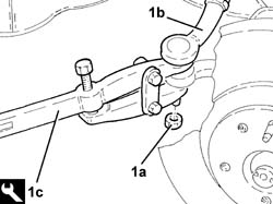
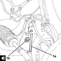
| 1b | Nut | FRONT ANTI-ROLL BAR JOINTS | M8 | (Front shock absorber fork side.) 4.1 ÷ 5.0 |
| Fastening | Component | Ø | Value(daNm) |
|---|---|---|---|---|
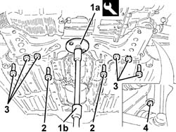
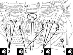
| 1 | Side bolt | ENGINE OR ROD ANCHORAGE BEAM | M12 | (Bodyshell side) 10.8 ÷ 13.2 |
| Fastening | Component | Ø | Value(daNm) |
|---|---|---|---|---|
| 2 | Rear bolt | ENGINE OR ROD ANCHORAGE BEAM | M10 | (Bodyshell side) 7.2 ÷ 8.8 |
| Fastening | Component | Ø | Value(daNm) |
|---|---|---|---|---|
| 2 | Rear bolts | ENGINE OR ROD ANCHORAGE BEAM | M12 | (Bodyshell side) 10.8 ÷ 13.2 |
| Fastening | Component | Ø | Value(daNm) |
|---|---|---|---|---|
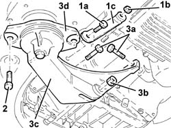
| 3 | Bolt | POWER STEERING BOX | M14 | (Front suspension crossmember side) 11.7 ÷ 14.3 |
| Fastening | Component | Ø | Value(daNm) |
|---|---|---|---|---|
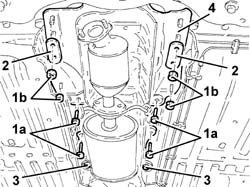
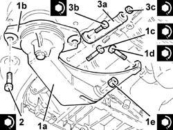
| 1c | Bolt | POWER UNIT RIGID REAR MOUNT | M12 | (Gearbox side) 6.8 ÷ 8.3 |
| Fastening | Component | Ø | Value(daNm) |
|---|---|---|---|---|
| 1d | Bolt | POWER UNIT RIGID REAR MOUNT | M12 | (Crankcase sump side) 6.8 ÷ 8.3 |
| Fastening | Component | Ø | Value(daNm) |
|---|---|---|---|---|
| 1e | Nut | POWER UNIT RIGID REAR MOUNT | M12 | (Gearbox side) 7.2 ÷ 8.0 |
| Fastening | Component | Ø | Value(daNm) |
|---|---|---|---|---|
| 2 | Bolt | INTERM RUBBER MOUNT | M8 | (Front suspension crossmember side) 3.2 ÷ 3.9 |
| Fastening | Component | Ø | Value(daNm) |
|---|---|---|---|---|
| 3b | Bolt | POWER UNIT RIGID REAR SUPPORT REINFORCEMENT ROD.... | M12 | (Power unit rear rigid mounting side) 6.8 ÷ 8.3 |
| Fastening | Component | Ø | Value(daNm) |
|---|---|---|---|---|
| 3c | Nut | POWER UNIT RIGID REAR SUPPORT REINFORCEMENT ROD.... | M8 | (Engine crankcase side) 2.4 |
| Fastening | Component | Ø | Value(daNm) |
|---|---|---|---|---|
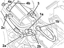
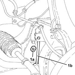
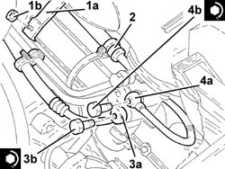
| 3b | Connector | PIPE FROM POWER STEERING BOX/EXCHANGER | M12 | (Power steering box side) 2.7 ÷ 3.3 |
| Fastening | Component | Ø | Value(daNm) |
|---|---|---|---|---|
| 4b | Connector | PIPE BTWN PUMP + POWER STEERING BOX | M14 | (Power assisted steering box side) 3.6 ÷ 4.4 |
| Fastening | Component | Ø | Value(daNm) |
|---|---|---|---|---|
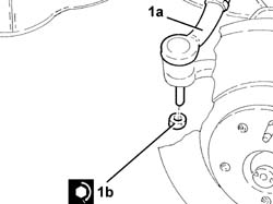
| 1b | Nut | ADJUSTABLE STEERING LINKS | M10 | (Front steering knuckle side) 3.2 ÷ 3.9 |
| Fastening | Component | Ø | Value(daNm) |
|---|---|---|---|---|
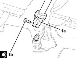
| 1b | Bolt | STEERING SHAFTS | M8 | (Power assisted steering box pinion side) 2.5 |
 | Type | Component | Name | Qty. |
|---|---|---|---|---|
| - | Fluid | POWER ASSISTED STEERING CIRCUIT | - | - |