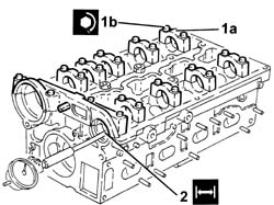
3025989 - 1016E10 single cylinder head, removed - overhaul
 | Name | Country |
|---|---|---|
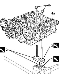
| 1 | Mount | 1.820.012.000 |
| Name | Country |
|---|---|---|
| 2 | Mount | 1.820.258.000 |
| Name | Country |
|---|---|---|
| 3 | Spacer | 1.820.267.000 |
 | Name | Connector |
|---|---|---|
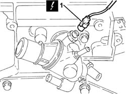
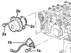
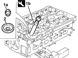
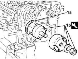
| 1 | Engine temperature sender unit | K36 |
| Name | Country |
|---|---|---|
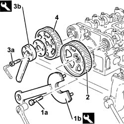
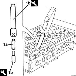
| 1b | Counter-torque | 1.822.146.000 |
| Name | Country |
|---|---|---|
| 1b | Counter-torque | 1.822.156.000 |
| Name | Country |
|---|---|---|
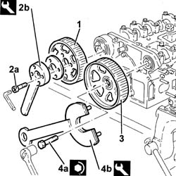
| 3b | Counter-torque | 1.822.155.000 |
 | Measurement | Value | |
|---|---|---|---|
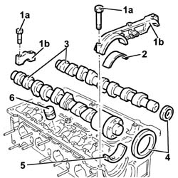
| - | Camshaft end float (mm) | 0.10 ÷ 0.23 |
| Name | Country |
|---|---|---|
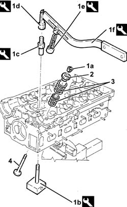
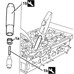
| 1b | Valve supports | 1.820.011.000 |
| Name | Country |
|---|---|---|
| 1c | Special nut | 1.820.049.000 |
| Name | Country |
|---|---|---|
| 1d | Mount | 1.821.124.000 |
| Name | Country |
|---|---|---|
| 1e | Chamber | 1.821.205.000 |
| Name | Country |
|---|---|---|
| 1f | Lever | 1.821.058.000 |
| Name | Country |
|---|---|---|
| 1b | Extractor | 1.821.208.000 |
| Name | Country |
|---|---|---|
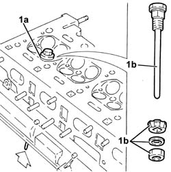
| 1b | Extractor | 1.821.176.000 |
| Measurement | Value | |
|---|---|---|---|
| - | Cylinder head lower plane planarity (mm) | 0.1 |
| Measurement | Value | |
|---|---|---|---|
| 1 | Combustion chamber minimum permissible height (mm) | 12.8 ÷ 13.2 |
| Measurement | Value | |
|---|---|---|---|
| - | Inlet stem diameter (mm) | 6.975 ÷ 6.990 |
| Measurement | Value | |
|---|---|---|---|
| - | Exhaust stem diameter (mm) | 6.960 ÷ 6.975 |
| Measurement | Value | |
|---|---|---|---|
| - | Valve contact band taper (-) | - |
| Measurement | Value | |
|---|---|---|---|
| - | Hydraulic tappeter outer diameter (mm) | 32.959 ÷ 32.975 |
| Measurement | Value | |
|---|---|---|---|
| - | Diameter of hydraulic tappet seats (mm) | 33.000 ÷ 33.025 |
| Measurement | Value | |
|---|---|---|---|
| - | Valve spring length released (mm) | External | 46.0 |
| Internal | 39.0 | ||
| Measurement | Value | |
|---|---|---|---|
| - | Outer valve spring height (mm) | ||
| Check load (daN) | 27.1 ÷ 29.4 | ||
| Measurement | Value | |
|---|---|---|---|
| - | Outer valve spring height (mm) | 24.5 | |
| Check load (daN) | 48.5 ÷ 52.4 | ||
| Measurement | Value | |
|---|---|---|---|
| - | Inner valve spring height (mm) | 29.5 | |
| Check load (daN) | 9.6 ÷ 10.6 | ||
| Measurement | Value | |
|---|---|---|---|
| - | Inner valve spring height (mm) | 20.0 | |
| Check load (daN) | 20.1 ÷ 22.1 | ||
| Measurement | Value | |
|---|---|---|---|
| - | Camshaft bearing diameter (mm) | 26.000 ÷ 26.015 |
 | Fastening | Component | Ø | Value(daNm) |
|---|---|---|---|---|
| 1b | - | - | - | - |
| Measurement | Value | |
|---|---|---|---|
| - | Camshaft bearing diameter (mm) | 26.045 ÷ 26.070 |
| Measurement | Value | |
|---|---|---|---|
| - | Valve guide outer diameter (mm) | 13.010 ÷ 13.030 |
| Measurement | Value | |
|---|---|---|---|
| - | Valve guide outer diameter oversize (mm) | 0.20 |
| Name | Country |
|---|---|---|
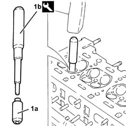
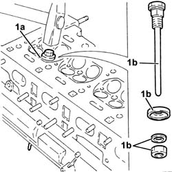
| 1b | Fitting tool | 1.821.254.000 |
| Measurement | Value | |
|---|---|---|---|
| - | Valve guide internal diameter (mm) | 7.022 ÷ 7.040 |
| Measurement | Value | |
|---|---|---|---|
| - | Valve seat outer diameter (mm) | Exhaust | 29.142 ÷ 29.157 |
| Intake | 35.135 ÷ 35.150 | ||
| Measurement | Value | |
|---|---|---|---|
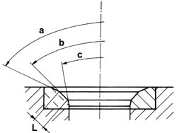
| - | Angle"a" valve seat upper band (-) | 150˚ |
| Measurement | Value | |
|---|---|---|---|
| - | Angle "b" contact band with valves (-) | 90˚ ± 10∍ |
| Measurement | Value | |
|---|---|---|---|
| - | Angle "c" valve seat lower band (-) | 30˚ |
| Measurement | Value | |
|---|---|---|---|
| - | Width "L" contact band with valves (mm) | Exhaust | 1.0 |
| Intake | 0.8 | ||
| Name | Country |
|---|---|---|
| 1b | Fitting tool | 1.821.206.000 |
| Name | Country |
|---|---|---|
| 1b | Valve supports | 1.820.011.000 |
| Name | Country |
|---|---|---|
| 1c | Special nut | 1.820.049.000 |
| Name | Country |
|---|---|---|
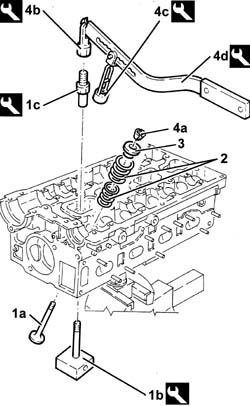
| 4b | Mount | 1.821.124.000 |
| Name | Country |
|---|---|---|
| 4c | Chamber | 1.821.205.000 |
| Name | Country |
|---|---|---|
| 4d | Lever | 1.821.058.000 |
| Fastening | Component | Ø | Value(daNm) |
|---|---|---|---|---|
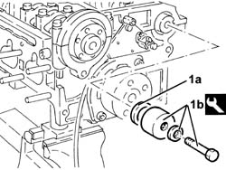
| 1b | - | - | - | - |
| Fastening | Component | Ø | Value(daNm) |
|---|---|---|---|---|
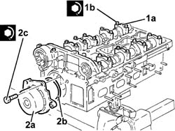
| 2c | - | - | - | - |
| Name | Country |
|---|---|---|
| 1b | Fitting tool | 1.821.228.000 |
| Name | Country |
|---|---|---|
| 1b | Fitting tool | 1.821.252.000 |
| Name | Country |
|---|---|---|
| 2b | Counter-torque | 1.822.155.000 |
| Fastening | Component | Ø | Value(daNm) |
|---|---|---|---|---|
| 4a | - | - | - | - |
| Name | Country |
|---|---|---|
| 4b | Counter-torque | 1.822.146.000 |
| Name | Country |
|---|---|---|
| 4b | Counter-torque | 1.822.156.000 |
| Fastening | Component | Ø | Value(daNm) |
|---|---|---|---|---|
| - | - | - | - | - |
| Fastening | Component | Ø | Value(daNm) |
|---|---|---|---|---|
| - | - | - | - | - |